background image

5-1

COMPONENT TESTING

Electrical Shock Hazard

Disconnect power before servicing.
Replace all parts and panels before operating.
Failure to do so can result in death or electrical shock.

Refer  to  page  4-3  for  the  procedure  for  ac-
cessing the exhaust fan motor.
1.  Unplug  microwave  oven  or  disconnect 

power.

2.  Disconnect  the  exhaust  fan  motor  con-

nector from the main harness connector.

3.  Set the ohmmeter to the R x 1 scale.
4.  Touch the ohmmeter test leads to the mo-

tor plug pins. The meter should indicate 
as follows:
Pin 1 (BK) to pin 2 (WH) = 17 ±5 

Ω

.

Pin 1 (BK) to pin 3 (RD) = 21 ±5 

Ω

.

EXHAUST FAN MOTOR

IMPORTANT: 

Before performing any tests on 

the microwave oven, be sure to observe the 
following:

Unplug  microwave  oven  or  disconnect 
power.
Remove  the  lead  wires  from  the  related 
component  before  conducting  any  of  the 
following tests.
Discharge  the  inverter  before  conducting 
any of the following tests.
All operational checks using microwave en-
ergy must be done with the microwave oven 
loaded with a minimum of 8 oz. (250 mL) of 
water in a microwave safe container.

Conduct  a  microwave  energy  test  after 
performing any tests or repairs to the mi-
crowave oven.
Check that all wire leads are in the correct 
position  before  operating  the  microwave 
oven.
Grasp wire connectors when removing the 
wire leads from microwave oven parts.
All testing must be done with an ohmmeter 
having  a  sensitivity  of  20,000  ohms-per- 
volt DC or greater, and powered by at least 
a 9-volt battery.

BASE THERMOSTAT

Refer to page 4-3 for the procedure for access-
ing the base thermostat.
1.  Unplug  microwave  oven  or  disconnect 

power.

2.  Disconnect  one  of  the  wires  from  the 

base thermostat terminals.

3.  Set the ohmmeter to the R x 1 scale.
4.  Touch  the  ohmmeter  test  leads  to  the 

thermostat  terminals.  The  meter  should 
indicate an open (infinite) circuit.

Содержание SPEEDCOOK GH6208 XR

Страница 1: ...CONSUMER SERVICES TECHNICAL EDUCATION GROUP PRESENTS KM 29 JOB AID Part No 8178545 SPEEDCOOK MICROWAVE OVEN WITH CONVECTION ...

Страница 2: ...ction The Wiring Diagram and Strip Circuits used in this Job Aid are typical and should be used for training purposes only Always use the Wiring Diagram supplied with the product when servicing the unit GOALS AND OBJECTIVES The goal of this Job Aid is to provide information that will enable the service technician to prop erly diagnose malfunctions and repair the Speedcook Microwave Oven With Conve...

Страница 3: ...hermostat Exhaust Fan Motor 4 3 Removing The Turntable Motor The Air Tube Vent Base 4 5 Removing The Relay Control Board And Line Fuse 4 7 Removing The Oven Door Components 4 10 Removing The Cavity Lamp And The Hood Light Switch Board 4 14 Removing The Primary Secondary And Monitor Interlock Switches 4 16 Removing The Oven From The Installation 4 17 Removing The Cabinet 4 18 Removing The FC Forced...

Страница 4: ...stor 5 7 Magnetron 5 8 Waveguide Thermostat 5 8 Exhaust Fan Motor Capacitor 5 9 Cooling Fan Motor 5 9 DIAGNOSTICS TROUBLESHOOTING 6 1 Primary Secondary And Monitor Interlock Switch Checkout Procedure 6 1 Troubleshooting Circuit Test Chart 6 2 Touch Panel And Relay Control Board Tests 6 2 Microwave Oven Power Output Test 6 3 Checking The Inverter 6 5 WIRING DIAGRAM STRIP CIRCUITS 7 1 Schematic Diag...

Страница 5: ...ards that can kill or hurt you and others All safety messages will follow the safety alert symbol and either the word DANGER or WARNING These words mean All safety messages will tell you what the potential hazard is tell you how to reduce the chance of injury and tell you what can happen if the instructions are not followed You can be killed or seriously injured if you don t immediately follow ins...

Страница 6: ...safety procedures should be exercised at all times Untrained personnel should not attempt service without a thorough review of test procedures and safety information contained in this Job Aid Whirlpool microwave ovens have a monitoring system designed to assure proper operation of the safety interlock systems The monitor switch will immediately cause the oven fuse to blow if the door is opened and...

Страница 7: ... or Abuse C Before turning on the microwave power for any service test or inspection within the microwavegeneratingcomponents check the magnetron waveguide or transmis sion line and cavity for proper alignment integrity and connections D Anydefective ormisadjusted components in the interlock monitor door seal and microwave generation and transmission systems shall be repaired replaced or adjusted ...

Страница 8: ...small emissions buttheymustbenogreaterthan4mw cm2 to allow for measurement uncertainty RF LEAKAGE TEST NOTE Enter leakage readings in space BE FORE and AFTER on the service document All microwave ovens exceeding the emission level of 4 mw cm2 must be reported to Dept of Service for Microwave Ovens immediately and the owner should be told not to use the microwave oven until it has been repaired com...

Страница 9: ...g bracket to the chassis ground otherwise this H V inverter circuit board will expose very high voltage and cause extreme DANGER Be suretohavepropergroundingbytheground ing plate and screws WARNING DISCHARGING HIGH VOLTAGE CAPACITORS For about 30 seconds after the oven is turned off an electric charge remains in the high voltage capacitors in the inverter power supply circuit board When replacing ...

Страница 10: ...RE LEVEL 8 28 KIT IF KIT FEATURE CODE C CSA APPROVED S CARRY IN WARRANTY EFFECTIVE 02 96 X IN HOME WARRANTY EFFECTIVE O2 96 YEAR OF INTRODUCTION R 2005 COLOR CODE B BLACK Q WHITE ON WHITE T BISCUIT Y GREY S STAINLESS STEEL ENGINEERING CHANGE 0 1 2 ETC WHIRLPOOL MODEL SERIAL NUMBER DESIGNATIONS MODEL NUMBER SERIAL NUMBER SERIAL NUMBER TR S 24 10018 MANUFACTURING SITE TR OXFORD MS SHUNDE CHINA YEAR ...

Страница 11: ...1 7 MODEL SERIAL NUMBER LABEL AND TECH SHEET LOCATIONS The Model Serial Number label and Tech Sheet locations are shown below Model Serial Number Label Tech Sheet Behind Decorative Panel ...

Страница 12: ...ication Yes Invalid Data Entry 3 Short Beeps and Indication on Display Technical Error Indication Pop Up Screen F With Error Number and Symbol Call for Service Diagnostic System Yes Independent Minute Timer Yes 4 rapid very short tones OVEN INTERIOR FEATURES Capacity 2 0 Cubic Feet Finish Non Stick Coating MW Cooking Power 1200 Watts IEC 705 Rating Grill Power 1500 Watts Turntable Yes 16 Diameter ...

Страница 13: ...Out each Speed 300 Noise Level Recirculation 67dBA Damper Yes Odor Removal filter Yes 2 Standard Charcoal Grease Filter Yes 2 Dishwasher Safe Blower Type Radial Shipped Recirculation mode EXTERIOR FEATURES Cooktop Light w Touch Control 2 Halogen Lamps 10 Watts Easy Access Separate Button Power Cord Length 3 Feet OTHER SPECIFICATIONS Electrical 120V Single Phase 60 Hz 1800 Watts For Use With 15 20 A...

Страница 14: ...ght Yes Separate Button Wattage 2 x 10 Watts Power Failure Indication Yes Standby Display Power Yes Invalid Data Entry 3 Short Beeps and Indication on Display Technical Error Indication Pop Up Screen F With Error Number and Symbol Call for Service Diagnostic System Yes OVEN INTERIOR FEATURES Capacity 2 0 Cubic Feet Finish Non Stick Coating MW Cooking Power 1200 Watts IEC 705 Rating Grill Power 150...

Страница 15: ...t 200 Exhaust CFM Out 300 Noise Level Recirculation 67dBA Damper Yes Blower Type Radial Shipped Recirculation mode EXTERIOR FEATURES Cooktop Light w Touch Control 2 Halogen Lamps 10 Watts Easy Access Separate Button Power Cord Length 3 Feet OTHER SPECIFICATIONS Electrical 15 20 Amp circuit 120V Single Phase 60 Hz 1800 Watts Domestic Use Only Yes Agency Approvals FCC CDRH UL CUL APPROVED ACCESSORIE...

Страница 16: ...1 12 NOTES ...

Страница 17: ...cm or above is recommended 30 76 2 cm is typical for 66 167 6 cm installation height Exact dimension may vary depending on type of range cooktop below A 2 x 4 wall stud B Grounded 3 prong outlet 66 167 6 cm min 12 30 5 cm min 13 33 0 cm max A B 30 76 2 cm typical 30 76 2 cm min 46 0 cm 18 1 4 18 1 8 m c 4 6 4 m c 9 5 7 15 1 2 39 4 cm 29 7 8 INSTALLATION INFORMATION INSTALLATION REQUIREMENTS ...

Страница 18: ...iances The microwave oven must be grounded In the event of an electrical short circuit grounding reduces the risk of electric shock by providing an escape wire for the electric current The microwave oven is equipped with a cord having a ground ing wire with a grounding plug The plug must be plugged into an outlet that is properly installed and grounded WARNING Improper use of the ground ing plug c...

Страница 19: ...opriate damper vent opening must be uncovered To Install Vent Deflector 1 Gently pull the rings and lift vent screen from the top of the oven A Top of oven B Vent screen C Rings B C A 2 With vent deflector oriented as shown wide side down slide it back and under the back edge of the vent opening 4 Secure vent deflector with 2 mounting screws 1 on each end A Vent opening B Vent deflector A B 3 When...

Страница 20: ...8205274 Mounting Screw Kit includes parts A G in Parts Supplied section Part Number 8205979 Vent Deflector Part Number 8205980 ACCESSORIES Filler Panel Kits are available from your deal er to use when installing this oven in a 36 91 4 cm or 42 106 7 cm wide opening The filler panels come in pairs Each panel is 3 7 6 cm wide See your authorized dealer or service center for details A Filler panels F...

Страница 21: ... 50 of the time OFF In contrast ovens utilizing this microwave system deliver the selected power level con tinuously This constant stream of microwave power helps to minimize overcooking of foods and messy food spatters A Oven door B Metal shielded window C Control panel D Fan Light and Night Light buttons E Halogen cooktop lights 2 F Exhaust vent for recirculation top surface of oven G Intake ven...

Страница 22: ...ction cooking The convection system is embedded in the wall of the oven cavity behind the pro tective screen The oven cavity and door will become hot The use of oven mitts is recom mended A Halogen bulb B Quartz bulb A B TURNTABLE The turntable can rotate in either direction to help cook food more evenly Do not operate the oven without having the turntable in place To Install 1 Remove tape from th...

Страница 23: ...see C below The display shows the Turntable On Off screen A Control panel B Interactive touch display C Turntable on off button A B Cook Method Food Type Kids Menu Most Used Time Temp Power MAIN MENU C Settings Info 2 Select Off thentouch OK Theturntable off indicator will appear on the display Repeat to turn the turntable back on ...

Страница 24: ...efault to 12 00 p m If the welcome screen appears at any other time a power failure has occurred Reset the clock if needed When the oven is not in use in standby mode the display shows the Main Menu and the date and time of day if they are set to be displayed see Clock and Date sections on page3 6 After 2 minutes of inactivity the display will go into sleep mode see Display Backlight sec tion on p...

Страница 25: ...portion of the screen which accepts no input A light to medium pressure touch of the fingertip will activate the menu choice A Title description region B Menu and selection settings input region C Command input region A B C MAIN MENU The Main Menu is displayed on the default screen From the Main Menu all automatic cooking programs can be activated all manual cooking can be programmed settings can b...

Страница 26: ...nu touch Settings Info 2 On Settings Info screen touch Date 3 On Date screen use Month or and Day or controls to set the month and day 4 Touch Adjust Year and change the year if desired To Hide Date On Date screen touch Hide Date The display will immediately return to the Main Menu Repeat to display the date DEMO MODE The Demo Mode highlights the features and capabilities of the oven in a slide sh...

Страница 27: ...left command area with the Timer countdown if both are in operation A Learning mode indicator A Kids Menu Cook Method Food Type Most Used Settings Info Time Temp Power To Activate Learning Mode The oven must be off 1 On the Main Menu touch Settings Info 2 On Settings Info screen touch More Choices 3 Touch Learning Mode 4 Touch On or Off to set 5 Touch OK TONES Tones are audible signals indicating ...

Страница 28: ...section if touched during cooking TIMER The Timer can be set in minutes and seconds upto99minutes 59seconds andcountsdown the set time NOTE The Timer does not start or stop the oven TheTimercountdowncanbeseeninfullscreen or in minimized view In minimized view the countdown is always visible A Minimized Timer countdown A Kids Menu Cook Method Food Type Most Used Settings Info Time Temp Power While ...

Страница 29: ...boost and off The status will be displayed for a few seconds while the settings are being adjusted COOKTOP LIGHT The cooktop light has 3 brightness settings high medium and low To Turn Light On Off Press LIGHT button repeatedly to cycle through the settings low medium high and off The status will be dis played for a few seconds while the settings are being adjusted NIGHT LIGHT The Night Light cont...

Страница 30: ...al picture of the estimated running time of a sensor cooking cycle It will appear at the beginning of sensor cooking functions Vertical bars appear below the word Sensing and show progress by the darkening of the bars left to right Some time after the progress bar appears it may be replaced by Maximum Time Remaining indi cator and the estimated remaining time which may fluctuate often When sensing ...

Страница 31: ... time to turn off TO SET COOKTOP LIGHT Press LIGHT button repeatedly to cycle through the settings high medium and low Press LIGHT a fourth time to turn off Press NIGHT LIGHT to turn Cooktop Light on at its lowest setting Press NIGHT LIGHT a second time to turn off Cooktop Light may still be used at higher settings and turned off without turning off the Night Light Touch and hold CANCEL control fo...

Страница 32: ...ouch control select food item select quantity if needed and then touch Start on the touch screen or START control CONTROL DESCRIPTION HOW TO USE Manual Control MICROWAVE TIME POWER Activates the manual microwave cooking programming mode Touch control follow screen prompts to enter cook time and adjust the microwave power if needed then touch Start on the touch screen or START control CONTROL DESCR...

Страница 33: ...ling fan motor O Motor capacitor P Monitor interlock switch Q Primary interlock switch R Relay control board S Line fuse 20 amp T Fuse holder U Hood cooktop lamps V Hood exhaust fan motor W Base thermostat closes at 140ºF 60ºC opens at 104ºF 40ºC X Turntable motor Y Touch panel board back and front views Z Cavity lamp AA Hood light switch BB FC motor CC FC thermostat opens at 329ºF 165ºC closes at...

Страница 34: ...the twelve T10 torx screws from the bottom cover 3 Partially lower the front of the cover and disconnect the connector from the turnta ble motor terminals then lower the cover the rest of the way 4 Disconnect the power connector from the bottom of the microwave oven 5 Unhook the bottom cover assembly from the microwave oven and remove it Screw 1 of 12 Bottom Cover Assembly Power Connector Turntabl...

Страница 35: ...eld b Pull the bulb so the pins are out of the socket holes and remove the bulb 5 To remove the exhaust fan motor a Remove the bottom cover assembly from the microwave oven see steps 4 and 5 on page 4 2 b Cut the wire tie from around the ex haust fan motor wires and disconnect the motor connector from the harness Continued on the next page Hood Lamp Sockets Light Shield L Blower Housing R Blower H...

Страница 36: ...ng from the motor and fan f Pull the blower off the motor shaft Exhaust Fan Motor Coupler g Remove the four screws from the housing cover and remove it from the motor Fan Housing Exhaust Fan Motor Housing Cover Screw 1 of 4 Exhaust Fan Motor Screws Motor U Bracket c Lift the bottom cover and remove the four indicated screws from the exhaust motor and U bracket ...

Страница 37: ... two T10 torx screws and washers 4 To remove the air tube vent base a Pull out on the two clips and pull the end of the air tube off the 90 vent base b Cut the wire tie from around the air tube see the left photo and pull the end of the air tube out of the door vent c Turn the 90 vent base to the right clockwise to unlock the four tabs from the slots in the chassis and pull the base off the chassi...

Страница 38: ...he tube so that the two tabs are out of alignment with the two locking arms on the vent base Slide the tube into the base and allow the tube to untwist so that the tabs clip into the arms and lock into place Twist Air Tube 90 Vent Base Front Tab Outside Of Arm Tab Locked Under Arm ...

Страница 39: ...l shock 1 Unplug microwave oven or disconnect power 2 Open the microwave oven door 3 Pull the two tabs and remove the center air flow screen from the top of the cabi net 4 Remove the four indicated screws from the right panel cover then pull the cover forward and remove it 5 Remove the screw from the right panel Center Air Flow Screen Continued on the next page Screws Right Panel Cover Right Panel...

Страница 40: ...ires will allow b Remove the line fuse from the fuse holder Right Panel Relay Control Board 6 To remove the relay control board a Lift the right panel and relay control board and unhook the two side T tabs and pull the right panel and relay con trol board forward as far as the wires will allow b Disconnect all of the wire connectors from the relay control board plugs c Squeeze the locking tabs on ...

Страница 41: ...4 9 P62 OR GY P61 3 WH P63 2 RD P65 3 RD P64 5 GY P67 3 YL P68 WH BK RD P66 5 RD 5BK P71 RD WH P73 2 WH P74 2 BK Relay Control Board W Connectors Wire Color Callouts ...

Страница 42: ...ottom of the oven press the locking arm on the user interface board UIB connector to disengage it and disconnect the connector from the chassis plug b Open the microwave oven door c Remove the screw at the top of the oven door hinge d Close the oven door but do not latch it Lift the door unhook the bottom hinge pin from the bracket and remove the door UIB Connector Oven Door Hinge Screw e Lay the ...

Страница 43: ...s and bottom of the oven door trim b Using a putty knife pry out on the out er door frame along the top to release the retainer clips Then use a regular screwdriver and pry the side of the in ner panel up and lift the panel assem bly out of the door frame 3 Side Screws Each side Pry Out Top Of Door Frame 2 Bottom Screws Pry Side Of Inner Panel Up Lift Inner Panel Remove Clips Along Top Of Door Fra...

Страница 44: ...board f Release the four clips from the LCD display board and remove it from the door frame g Remove the two T20 torx screws and washers from the door handle and re move the handle h Remove the three T20 torx screws from the top trim of the door and re move the trim Electronic Control Cover Screws 4 Board Connectors User Interface Board LCD Display Board User Interface Board Screws LCD Display Boa...

Страница 45: ...4 13 i Lift the door glass assembly off the door frame Remove Door Glass Door Glass Assembly ...

Страница 46: ...r air flow screen from the top of the cabinet 3 To remove the cavity lamp socket a Remove the T10 torx screw from the cavity lamp cover Center Air Flow Screen Cavity Lamp Cover Screw b Remove the clip from the cavity lamp socket and remove the lamp and socket Clip Socket Hood Light Switch Board Screws Washers 4 To remove the hood light switch board a Lower the bottom cover see page 4 2 for the pro...

Страница 47: ...4 15 c Disconnect the hood light switch board connector from the chassis and re move the board Hood Light Switch Board Connector Hood Light Switch Board ...

Страница 48: ... Remove the T10 torx screw for the switch es you are servicing 6 Disconnect the wires from the switch ter minals 7 Carefully bend the two locking tabs so they disengage from the switch and pull the switch off the holder pins Secondary Switch Screw Primary Monitor Switch Screw 5 Insert a small screwdriver blade into each of the switch actuator slots and rotate the switch actuators to unlock them th...

Страница 49: ...perating Failure to do so can result in death or electrical shock 1 Unplug microwave oven or disconnect power 2 Open the cabinet doors over the micro wave oven 3 While supporting the bottom of the mi crowave oven locate and remove the two mounting bolts from the top of the microwave oven NOTE The unit will ro tate down when these two bolts are re moved 4 Using two or more people carefully rotate t...

Страница 50: ...om the top of the cabinet 6 Remove the T10 torx screw from the power cord cover and remove the cover 4 Remove the T10 torx screws from the left and right air flow screens and remove the screens from the top of the cabinet Left Right Air Flow Screen Screws 7 Remove the two T10 torx screws from the left and right sides of the cabinet and the eight screws from the rear cabinet flange Cabinet Top Scre...

Страница 51: ...e 4 18 for the procedure 4 To remove the FC thermostat a Disconnect the two wires from the thermostat terminals b Remove the two screws from the ther mostat and remove it from the micro wave oven 5 To remove the FC motor a Disconnect the two wires from the FC motor terminals b Remove the three T10 torx screws from the FC motor bracket and remove the motor from the heater cover Red Wire Brown Wire ...

Страница 52: ...ve the FC fan motor Clip e Remove the two screws from the FC motor bracket and remove the bracket from the motor FC Motor Bracket Screws c Pry the clip off the FC motor shaft and remove the fan blade and the flat washer below the blade from the shaft see the top left photo d Remove the T10 torx screw from the FC ring heater bracket and the three T10 torx screws from the inner heater cover then pul...

Страница 53: ...4 21 e Removethetwo5 16 hex headscrews from the FC ring heater bracket on the inner cover and remove the element FC Ring Heater Screws ...

Страница 54: ...8 for the procedure 4 Peel back the foil from the rear of the top cover 5 Remove the six indicated T10 torx screws from the top cover 6 Lift the top cover by the bracket and re move the cover from the microwave oven 7 To remove the FC thermistor a Squeeze the ends of the clip and re move the clip and the FC thermistor b Remove the FC thermistor wires from the standoffs at the top of the chassis FC...

Страница 55: ...tat and humidity sensor b Disconnect the wires from the cavity thermostat terminals c Remove the sensor wires from the standoffs at the top of the chassis Clip Mounting Bracket Humidity Sensor Cavity Thermostat d Disconnect the humidity sensor con nector at relay control board plug P68 and remove the bracket with the cavity thermostat and humidity sensor Cavity Thermostat RD BU BU Humidity Sensor ...

Страница 56: ...re 3 Remove the cabinet from the microwave oven see page 4 18 for the procedure 4 Remove the top cover from the micro wave oven see page 4 22 for the proce dure Grill Cover Grill Thermostat b Remove the two screws from the ther mostat terminals and remove the thermostat Grill Thermostat 6 To remove the grill elements a Remove the two T10 torx screws from the grill element cover lift the cover and ...

Страница 57: ...low the remaining steps for re moving the Quartz Grill Heater Halo gen Grill Element c Depending on which element you are removing press down on the locking tabs and pull the wire connectors off the ends of the quartz grill heater or the halogen grill element see above photo NOTE The element glass is very fragile so be careful when re moving and installing connectors on the terminals e Open the mi...

Страница 58: ...connect the white wire on the pow er supply cord from the AC line filter board at terminal P31 and the black wire at terminal P32 b Remove the chassis screw from the green ground wire on the power sup ply cord AC Line Filter Power Supply Cord 6 To remove the AC line filter a Disconnect the white and black power supply cord wires from the AC line fil ter board see above b Disconnect the brown wire ...

Страница 59: ... the cabinet from the microwave oven see page 4 18 for the procedure FC Thermoactuator 4 To remove the FC thermoactuator a Remove the right cover and panel see page 4 7 for the procedure b Remove the top secondary door switch assembly see page 4 16 for the procedure c Press the locking tabs and disconnect the two wire connectors from the FC thermoactuator terminals d Using a 90 T10 Allen wrench re...

Страница 60: ... ter board this will allow enough slack in the wires to remove them from the wire channel later d Remove the three air duct screws and remove the air duct from the chassis NOTE Remove the channel wires from the air duct as you remove the duct from the unit Magnetron Thermistor Screw Mag Thermistor Connector P74 Control Board e CAUTION Discharge the inverter board see step 4 on page 4 31 for the pr...

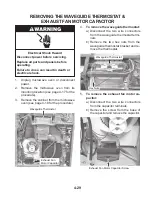
Страница 61: ...he cabinet from the microwave oven see page 4 18 for the procedure Waveguide Thermostat Waveguide Thermostat Exhaust Fan Motor Capacitor 4 To remove the waveguide thermostat a Disconnect the two wire connectors from the waveguide thermostat termi nals b Remove the two hex nuts from the waveguide thermostat bracket and re move the thermostat 5 To remove the exhaust fan motor ca pacitor a Disconnect...

Страница 62: ... for the procedure 3 Remove the cabinet from the microwave oven see page 4 18 for the procedure 6 Remove the two screws and washers from the cooling fan motor and remove it from the housing 4 Disconnect the cooling fan motor con nector from the main harness see the top right photo 5 Remove the three T10 torx screws from the cooling fan motor housing and re move the housing from the chassis Cooling...

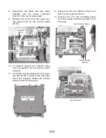
Страница 63: ...e chassis see the photo at the top right column and the shaft against either of the two magnetron filament ter minals for approximately 5 seconds to discharge the inverter board 5 Disconnect the two magnetron filament wires from the magnetron terminals 6 Remove the T10 torx screw from the bot tom of the inverter board housing 7 Slide the bottom of the inverter board housing assembly out and unhook...

Страница 64: ... the black and blue wires CN702 and the 3 wire connector CN701 from the inverter board 9 Remove the screw from the green yel low ground wire on the inverter board E701 Ground Screw Connector CN701 BK BU CN702 Inverter Board 12 Disconnect the two filament wires from the inverter board at CN703 13 Remove the T10 torx mounting screw from the inverter board and unclip it from the base Mounting Base Cl...

Страница 65: ...re 3 Remove the cabinet from the microwave oven see page 4 18 for the procedure 5 Push out on the three outside tabs of the relay board holder and lift the relay board out of the holder as far as the wires will allow Relay Board Relay Board Holder Tabs 4 CAUTION Discharge the inverter board see step 4 on page 4 31 for the proce dure Relay Board 6 Disconnect the wire connectors from the relay board...

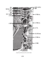
Страница 66: ...4 34 GR BU WH BU 2 BU 2 RD 2 BR BU GY BK BK BR 4 Wires 3 Wires 3 Wires 2 WH 10 Wires 3 YL Relay Board W Connector Wire Color Callouts ...

Страница 67: ...the following tests Discharge the inverter before conducting any of the following tests All operational checks using microwave en ergy must be done with the microwave oven loaded with a minimum of 8 oz 250 mL of water in a microwave safe container Conduct a microwave energy test after performing any tests or repairs to the mi crowave oven Check that all wire leads are in the correct position befor...

Страница 68: ...ne of the wires from the turntable motor terminals 3 Set the ohmmeter to the R x 10K scale 4 Touch the ohmmeter test leads to the motor terminals The meter should indi cate 2 2 K 0 5 KΩ LINE FUSE Refer to page 4 7 for the procedure for access ing the line fuse 1 Unplug microwave oven or disconnect power 2 Disconnect one of the wires from the fuse holder terminals 3 Set the ohmmeter to the R x 1 sc...

Страница 69: ... secondary switch normally open The meter should indi cate an open infinite circuit 5 Touch the ohmmeter test leads to the terminals of the monitor switch normal ly closed The meter should indicate a closed 0 Ω circuit NOTE Pressing the actuator button on the switches should result in opposite readings normally open should read closed and nor mally closed should read open Refer to page 4 19 for th...

Страница 70: ...connect one of the wires from the FC motor terminals 3 Set the ohmmeter to the R x 100K scale 4 Touch the ohmmeter test leads to the FC motor connector pins The meter should indicate 21 5 5 Ω Refer to page 4 19 for the procedure for ac cessing the FC ring heater 1 Unplug microwave oven or disconnect power 2 Disconnect one of the wires from the FC ring heater terminals 3 Set the ohmmeter to the R x...

Страница 71: ...ermostat a Set the ohmmeter to the R x 1 scale b Touch the ohmmeter test leads to the thermostat terminals The meter should indicate a closed 0 Ω circuit 4 To test the humidity sensor a Set the ohmmeter to the R x 1K scale b Touch the ohmmeter test leads to sen sor connector pins 1 and 3 and then 2 and 3 The meter should indicate ap proximately 2 8 KΩ 77 F 25 C Refer to page 4 22 for the procedure...

Страница 72: ...ter to the R x 1 scale 4 Touch the ohmmeter test leads to the element terminals The meter should in dicate as follows Halogen Grill Element 2 1 Ω Softstart Quartz Element 6 2 Ω Quartz Grill Heater 29 5 Ω Refer to page 4 24 for the procedure for ac cessing the grill thermostat 1 Unplug microwave oven or disconnect power 2 Disconnect one of the wires from the thermostat terminals 3 Set the ohmmeter ...

Страница 73: ...thermistor connector from the relay control board 3 Set the ohmmeter to the R x 1K scale 4 Touch the ohmmeter test leads to the thermistor connector pins The me ter should indicate 10 KΩ 5 77 F 25 C Refer to page 4 27 for the procedure for ac cessing the FC thermoactuator 1 Unplug microwave oven or disconnect power 2 Disconnect one of the wires from the thermoactuator terminals 3 Set the ohmmeter ...

Страница 74: ...on filament terminals 3 Set the ohmmeter to the R x 1 scale 4 Touch the ohmmeter test leads to the filament terminals The meter should in dicate less than 1 Ω Filament Terminals WAVEGUIDE THERMOSTAT Refer to page 4 29 for the procedure for ac cessing the waveguide thermostat 1 Unplug microwave oven or disconnect power 2 Disconnect one of the wires from the thermostat connectors 3 Set the ohmmeter ...

Страница 75: ...trical Shock Hazard Disconnect power before servicing Replace all parts and panels before operating Failure to do so can result in death or electrical shock Refer to page 4 29 for the procedure for ac cessing the exhaust fan motor capacitor 1 Unplug microwave oven or disconnect power 2 Disconnect the wires from the terminals 3 Set the ohmmeter to the R x 10K scale 4 Touch the ohmmeter test leads t...

Страница 76: ...5 10 NOTES ...

Страница 77: ...nplug microwave oven or disconnect power 2 Disconnect the wires at the Secondary Interlock Switch 3 Check from the common terminal blue wire to the normally open terminal white blue wires Monitor Interlock 1 Unplug microwave oven or disconnect power 2 Disconnect the wires at the Monitor Interlock Switch 3 Check from the common terminal blue wire to the normally closed terminal white red wires Cont...

Страница 78: ... Display Explanation UIB SW ver Version number of UIB user interface board software PB SW Ver Flash Version number of power board relay control board software FC thermistor ºC The temperature ºC measured by FC forced convection thermistor maximum 250ºC UIB thermistor ºC The temperature ºC measured by UIB user interface board thermistor ranges 5ºC above below room temperature if oven has not been u...

Страница 79: ...the door control assembly 4 Plug in microwave oven or reconnect power F3 H1 Humidity sensor 1 Unplug microwave oven or disconnect power 2 Check connection to relay control board 3 Replace humidity sensor 4 If problem persists replace relay control board 5 Plug in microwave oven or reconnect power F3 T1 UIB user interface board thermistor 1 Unplug microwave oven or disconnect power 2 Check the conn...

Страница 80: ... replacing inverter if there is no voltage replace relay control board 10 Plug in microwave oven or reconnect power F9 Relay control board communications error 1 Unplug microwave oven or disconnect power 2 Check the communications cable from P66 to P56 between relay control board and relay board 3 If problem persists replace the relay board and relay control board 4 Plug in microwave oven or recon...

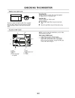
Страница 81: ...relay control board and wiring No control signal Check relay control board and wiring Check the 1200W Inverter NOTE Do not try to repair the inverter board nor try to make any adjustments to the board Check wiring to 1200W inverter 1 Unplug microwave oven or disconnect power 2 Visually inspect 4 connectors on the 1200W inverter board CN701 CN702 CN703 E701 to see whether there are signs of overhea...

Страница 82: ...6 6 NOTES ...

Страница 83: ... R 7 0 9 4 2 5 P N H C F y a l e R 5 0 9 4 F C C F W 5 5 1 8 P 5 W 0 5 1 8 P 6 FC Ring Heater D N G R F H W BK r o t o M r o t i c a p a C t s u a h x E d o o H r o t o M n a F H T C F H T C F n o i t c e v n o C d e c r o F C F r o t a u t c a o m r e h T C F n o i t c e v n o C d e c r o F C F r o t o M n a F R F H K B F C A F C F A m 0 0 5 e s u F L 4 7 P 1 FC Thermistor R B 2 39 BU 35 BR 56 W ...

Страница 84: ...t QUARTZ GRILL HEATER L BK Filter BR Fuse 20 Amp Primary Interlock Switch Grill Thermostat W R W BU Quartz Grill Element Heater Relay 4904 Relay Board 2 1 BU BU W Secondary Interlock Switch BU BU Cavity Thermostat Filter W N BU Waveguide Thermostat BR SOFTSTART QUARTZ TUBE BU Cavity Thermostat BU Secondary Interlock Switch 2 1 W L N W Filter Halogen Grill Element BU BK BK Filter BR Fuse 20 Amp Pri...

Страница 85: ...vity Thermostat BR BU BU N W L BK Filter Filter Fuse 20 Amp Waveguide Thermostat 4P54 BR R 2P83 5P81 TURNTABLE MOTOR 4P54 W TT 1P53 Relay Board BR W 5P81 R G BR BR P52 P51 Cavity Thermostat BR BU BU N W L BK Filter Filter 6P81 Fuse 20 Amp TTRelay 4906 Waveguide Thermostat R DOOR OPEN OVEN CAVITY LIGHT IS ON L N Fuse 20 Amp BR W BK BR B R P51 P52 2P55 Fuse 500mA Inverter 4170 4121 Fuse 500mA 3P55 P...

Страница 86: ... Fuse 500mA Inverter 4170 4121 Fuse 500mA 3P55 P61 1 2 3 Relay Control Board Relay Board 3 6 P OR 1P62 1 2 Primary Interlock Switch Cavity Lamp 1P55 BR HOOD EXHAUST FAN ON AUTO L N Fuse 20 Amp BR W BK BR BR P51 P52 BU BU G Relay Board 4 P54 HF 2P82 3P82 W R BR W W BK BU BU BU 1P82 5P81 4P81 Filter Base Thermostat Motor Capacitor Filter Cavity Thermostat 7P81 8P81 R Waveguide Thermostat R R R ...

Страница 87: ...uartz heater Both bulbs operate to provide the 1500 Watts of cooking power for the grill The third element is a 60 volt 600 watt Soft Start quartz element This element is not used for grilling heat It is in the circuit with the other elements to control inrush current during grill ing Once the current stabilizes in the circuit a relay on the microcomputer board opens and eliminates power to the el...

Страница 88: ...olled by its relay during combination grill and microwave cooking Whengrillingbegins thequartzheater relay closes and activates the quartz heater element The quartz heater element cycles on for up to 40 of the grilling time depending on the type of food that is being grilled Combination Grilling The Quartz Heater Relay Opens Closes Intermittently Depending On The Type Of Food Being Grilled of the ...

Страница 89: ...l assembly reaches 293 F 145 C The thermostat is located on the grill element cover and is accessible by removing the cabinet b Remove the halogen and quartz heat er elements by sliding them out of the holes in the mounting bracket Grill Element Guard To remove the quartz or halogen grill ele ment from the oven cavity a Pull the guard down and remove it from the top of the oven cavity Halogen Elem...

Страница 90: ... the two wires from the magnetron terminals 2 Place 1 liter of water into the oven cavity 3 Program the oven for 1 minute at full power 4 Press START While the oven is operating the amp meter should indicate between 1 0 and 1 7 amps After approximately 23 seconds the oven will turn off and the display will indicate an F7 error code 5 If the current is within the range indicated in the chart procee...

Страница 91: ...0 4 and 0 8 amps After ap proximately 3 seconds the oven will turn off and the display will indicate an F7 error code 4 If the current is within the range indicated in the chart the inverter power supply is working properly If not replace the inverter board CONNECTORS METER READING SYMPTOM Unplug Relay Control Board P65 CN701 0 4 to 0 8 Amperes Oven turns off in 3 seconds F7 error code displayed P...

Страница 92: ...8 6 NOTES ...

Страница 93: ...8 7 NOTES ...

Страница 94: ...8 8 NOTES ...

Страница 95: ...RIZED SERVICER IN CANADA FOR PRODUCT SPECIFICATIONS AND WARRANTY INFORMATION CALL 1 800 461 5681 FOR TECHNICAL ASSISTANCE WHILE AT THE CUSTOMER S HOME CALL THE TECHNICALASSISTANCE LINE 1 800 488 4791 HAVE YOUR STORE NUMBER READY TO IDENTIFY YOU AS AN AUTHORIZED SERVICER FOR WHIRLPOOL PRODUCTS 1 800 253 1301 FOR KITCHENAID PRODUCTS 1 800 422 1230 FOR ROPER PRODUCTS 1 800 447 6737 FOR LITERATURE ORD...

Страница 96: ...CORPORATION ...
Отзывы: