background image

6 - INSTRUCTIONS FOR USE

0803_GB_42

- GAS KITCHENS WITH PILOT

04/2008

a service agreement contract is recommended.

6.9 Recommendations for the treatment of 
stainless “steel industrial” kitchens

6.9.1 Useful information on “stainless steel”

Industrial kitchens are generally made of “stainless steel” having the
following material codes:

•  1.4016 or 1.4511 = magnetizable chromed steels

•  1.4301, 1.4401 and 1.4571 =  non-magnetizable chromed steels

Chromed steels have favourable thermo-technical characteristics. In
fact, they have less of a tendency to warp due to the effect of heat.

Chrome-nickel steels, instead, have good corrosion resistance features.

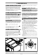
“Stainless steel” corrosion resistance is given by an inactive coat that
builds up on the surface by coming into contact with oxygen.

The oxygen in the air is already enough to build up the inactive coat
that allows automatic removal of anomalies and damage due to
mechanical actions. The inactive coat builds up or re-builds up faster
if the steel comes in contact with running water containing oxygen.

A more powerful effect is given by oxidative acids (nitric acid, oxalic
acid). These acids are used if the steel has undergone strong chemi-
cal stresses, hence generally losing its inactive coat.

The inactive layer can be chemically damaged or jeopardized by
reducing agents (oxygen consumption) if they come in contact with
the steel, concentrated or at high temperatures. These active sub-
stances include for instance:

•  saline and sulphurous substances

• chlorides 

(salts)

•  concentrated spices such as mustard, vinegar essences, soup

cubes, kitchen salt solutions, etc.

More damage can be caused by:

•  outside rust (i.e. from other components, tools or incipient rust)

•  iron particles (i.e. file dust)

•  contact with non-ferrous metals (element build up)

•  lack of oxygen (i.e. no air inlet, water lacking oxygen).

6.9.2 Warnings and advice for maintenance of “stain-
less steel” appliances

•  “Stainless” steel equipment surfaces must be kept clean and in

contact with air at all times. When not running, keep appliance
doors open so as to allow air to run through it.

•  Regularly remove calcium , grease, starch, and egg white deposits

where rust may build up if there is lack of air. Do not use bleach-
ing products or products containing chloride. Follow all indica-
tions given by the company concerning special soaps and clean-
ing methods to be used for the appliance. If no specific cleaning
recommendations are available, it is necessary, however, to use
detergents having a low chloride content. After cleaning, remove
all soap residues with plenty of clean water and thoroughly dry
the surfaces.

•  Minimize contact of “stainless steel” with concentrated acids,

spices, salts, etc. Even acid vapours coming from cleaning the tiles
favour “stainless steel” corrosion.

•  Particularly for pots and multiple appliances, it is not recom-

mended to load the cooking chamber only with food having a
high salt content.

It is preferable to cook different food together, i.e. fatty dishes
or vegetables containing acids.

•  Avoid damaging the “stainless steel” surface, in particular with

different metals. Residues from other metals help build up the
formation of chemical microelements that may cause rust. At any
rate, it is appropriate to avoid contact between iron and steel
since it produces rust. Any contact between “stainless steel” and
iron (steel wool, pipeline chips, chalybeate waters) can start cor-
rosion phenomena. 

•  As for mechanical cleaning, it is recommended to use only steel

wool or natural, plastic or steel bristle brushes. Steel wool or
brushes with “stainless steel” can cause rust due to rubbing.
Newly formed rust spots can be removed with slightly abrasive liq-
uid soaps or fine-grained sand paper. Larger rust spots can be
removed with 2-3% of hot oxalic acid solution. If these cleaning
products do not do the job, a nitric acid (10%) treatment is
required.

Attention! These treatments can be carried out only by
expert personnel according to current regulations!

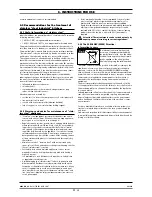
6.9.3 The 2002/96/EC (WEEE) Directive: 
information to users

This informational note is meant only
for owners of equipment marked with
the symbol shown in fig. A on the adhe-
sive label featuring the technical specifi-
cations applied on the actual product
(the label also giving the serial number).

This symbol indicates that the product is classified, according to the
regulations in force, as an item of electrical and electronic equip-
ment and conforms to EU Directive 2002/96/EC (WEEE) meaning
that, at the end of its service life, it must be treated separately from
domestic waste, i.e. it must be handed in free of charge to a separa-
te waste electrical and electronic equipment collection centre or
returned to the reseller when buying a new equivalent item of
equipment.
The user is responsible for delivering the unit at the end of its life
to the appropriate collection facilities. Failure to do so shall result in
the user being subject to the penalties prescribed by the legislation
in force on waste.
Suitable separated collection so that the unit no longer used can be
sent off for environmentally compatible recycling, treatment and
disposal helps avoid possible negative effects on the environment
and on health and facilitates the recycling of the product's compo-
nent materials.

For more detailed information on available collection systems, con-
tact the local waste disposal service or the shop you purchased the
unit from.
Producers and importers fulfil their responsibility for environmental-
ly compatible recycling, treatment and disposal both directly and by
joining a collective scheme.

17

· 20

Fig. A

Содержание ADN 606

Страница 1: ...Instructions for installation use e maintenance GAS KITCHENS WITH PILOT 0803_GB_42 ADN 606 ADN 607 ADN 608 ADN 610 ADN 609 ADN 611 ADN 631 04 2008 ...

Страница 2: ...0803_GB_42 GAS KITCHENS WITH PILOT 2 20 04 2008 CHARACTERISTICS Supplied by Date Customer Service FAX e mail ...

Страница 3: ...ement of pilot injector of gas oven GN 2 1 12 5 2 Maintenance 12 5 3 Replacing parts 13 5 3 1 Open flame gas cock 13 5 3 2 Open flame thermocouple 13 5 3 3 Gas valve gas oven GN 2 1 13 5 3 4 Plug gas oven GN 2 1 13 5 3 5 Thermocouple gas oven GN 2 1 13 5 3 6 Main burner gas oven GN 2 1 13 5 3 7 Cock solid top 13 5 3 8 Plug solid top 13 5 3 9 Thermocouple solid top 13 5 3 10 Heating elements of ele...

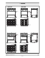
Страница 4: ...00 ADN 606 ADN 607 200 400 200 800 245 178 5 276 5 700 34 1000 200 300 300 200 178 5 245 276 5 34 700 910 45 45 34 1000 710 45 45 34 800 545 55 25 496 150 42 60 678 700 0 0 0 0 0 0 0 0 0 0 0 0 0 0 0 0 0 0 0 0 0 0 Electric power Gas 1 2 Data plate Gas 1 2 Electric power Gas 1 2 Electric power Data plate Data plate Electric power Gas 1 2 Data plate Gas 1 2 Gas 1 2 Data plate Gas 1 2 Gas 1 2 Data pla...

Страница 5: ...34 700 ADN 611 ADN 609 25 545 55 690 496 60 150 678 42 700 800 710 45 45 79 34 910 45 45 34 79 1000 200 400 200 800 700 34 79 276 5 245 178 5 1000 200 300 300 200 178 5 245 276 5 34 700 79 0 0 0 0 0 0 0 0 0 0 0 0 0 0 0 0 0 0 0 0 0 0 0 0 Data plate Gas 1 2 Gas 1 2 Gas 1 2 Data plate Gas 1 2 Data plate Data plate Gas 1 2 Electric power Electric power Gas 1 2 Data plate Gas 1 2 Electric power Data pl...

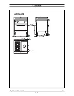
Страница 6: ...1 DIAGRAM 0803_GB_42 GAS KITCHENS WITH PILOT 6 20 04 2008 800 34 700 496 25 55 545 60 678 150 700 800 34 45 710 7 6 5 4 321 0 0 45 ADN 631 0 Data plate Gas 1 2 Gas 1 2 Data plate ...

Страница 7: ... x 700 x 900 1000 x 700 x 900 800 x 700 x 900 800 x 700 x 900 1000 x 700 x 900 800 x 700 x 900 1000 x 700 x 900 800 x 700 x 900 1000 x 700 x 900 800 x 700 x 900 1000 x 700 x 900 N 51BS3547 51BS3547 51BS3547 51BS3547 51BS3547 51BS3547 51BS3547 51BS3547 51BS3547 51BS3547 51BS3547 51BS3547 51BS3547 51BS3547 51BS3547 51BS3547 2 CHARACTERISTICS OF THE APPLIANCES 3 TECHNICAL DATA These appliances are us...

Страница 8: ...7 mbar 24 8 37 2 31 5 43 9 25 1 20 8 31 2 27 5 37 9 kW kW kW kW kW kW kW kW kW II2H3 A m3 h kW kW No of nozzles pilot burner G20 G30 G31 7 Open Open Open B Ø 100 8 4 0 1 2 C Ø 120 12 6 0 1 8 Gas oven GN 2 1 16 6 5 0 423 0 313 0 741 0 552 145 Adjustable 100 45 198 135 27 19 35 20 9 Open 0 635 0 470 185 Adjustable 125 75 27 19 2 60 3 94 3 33 4 65 2 66 2 20 3 30 2 91 4 01 1 94 2 91 2 46 3 44 1 96 1 6...

Страница 9: ...ble wall and thermal insulation is equipped with an insulated handle and a hinge with balanced spring The insulation of the cooking chamber is rockwool Gas version GN 2 1 The tubular burners are in stainless steel and are resistant to ther mal and mechanical stress Gas is supplied through a safety valve with a thermostat Temperature adjustment between 150 C and 300 C is made with the thermostat Th...

Страница 10: ...e appliance is in standby status The calorific power value can be requested from the local gas company The nominal power and the minimum power with respect to the nominal pressure are obtained by consulting the table for the adjustment of the gas passage table 1 WARNING There is no pre adjustment device for the nominal power E Power Operating calorific value 4 INSTALLATION INSTRUCTIONS 5 SET UP FO...

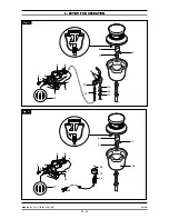
Страница 11: ...5 SET UP FOR OPERATION 0803_GB_42 GAS KITCHENS WITH PILOT 04 2008 11 20 6 8 7 9 22 5 4 21 3 11 13 12 14 17 1 2 A 18 0 Fig 1 6 8 7 22 5 4 21 3 14 17 1 2 10 A 18 23 0 Fig 2 ...

Страница 12: ...g the pilot on the the injec tor holder cup lift up the pilot to a more convenient position for unscrew the nut pos 11 fig 1 pull down the nut together the pipe and the bicone pos 13 fig 1 unfix the injector and replace the injector with one able for the type of gas see table 1 install in rever se order After the replacement check the seal using a leack detector spray 5 1 13 Setting reduced capaci...

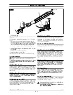
Страница 13: ... After the replacement check the seal using a leack detector spray 5 3 4 Plug gas oven GN 2 1 Unscrew the fastening screws and remove the lower panel extract the ignition wire and unscrew the screws pos 15 fig 3 unscrew the screw pos 20 fig 3 fixing the pilot on the support pull down the pilot to a more convenient position and put in a new piece pos 16 fig 3 install in reverse order 5 3 5 Thermoco...

Страница 14: ...ical mains To remove the heating element pos 6 fig 6 remove the rear bulk head unscrew the screws fixing the the heating element to the oven pull the heating element forward with relative wires Disconnect the wires and install a new heating element in reverse order 5 3 12 Fan of of electric oven GN 1 1 Unplug the appliance from the electrical mains To replace the fan remove the back unscrew the si...

Страница 15: ...safety standards WARNING Attention The manufacturer declines all responsibility concern ing mistakes included in these instructions due to translating or printing errors the manufacturer also reserves the right to change the product as he see fits though without changing its essential features The manufacturer declines all responsibility for any non compliance with the provisions contained in this...

Страница 16: ... must be done between the max and min supply position of easily selectable interme diate levels To turn the burner off during normal operation turn the knob as far as 0 6 7 Turning the appliance off in case of breakdown 6 7 1 What to do in case of failure In case of breakdown or malfunctioning or failure close the gas cock and the oven Close the connecting cock of the unit and switch off any elect...

Страница 17: ... acid vapours coming from cleaning the tiles favour stainless steel corrosion Particularly for pots and multiple appliances it is not recom mended to load the cooking chamber only with food having a high salt content It is preferable to cook different food together i e fatty dishes or vegetables containing acids Avoid damaging the stainless steel surface in particular with different metals Residue...

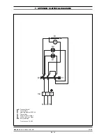
Страница 18: ... P4 4 F1 B2 P3 5 P4 6 P6 P5 P2 7 2 1 3 4 1 3 5 2 4 6 1 3 5 2 4 6 R2 R1 H1 H2 F2 230V 3 14 75 A 1 3 5 2 4 6 R1 R2 230V 25 7 A 1 3 5 2 4 6 R1 R2 L1 N 1 mA 2 3 4 1 mA 2 3 4 L1 L2 L3 ADN 609 ADN 611 mA B1 B2 F1 F2 R1 2 H1 H2 Terminal board Switch Commutator Thermostat Security thermostat Heating element 980 W Green indicator light Yellow indicator light Total power 5 9 kW ...

Страница 19: ...9 20 04 2008 7 APPENDIX ELECTRICAL DIAGRAMS mA N L1 PE B1 1 2 3 H1 H2 R1 F1 MV mA B1 R1 F1 H1 H2 MV Terminal board Commutator Heating element 2500 W Thermostat Green indicator light Yellow indicator light Motorized fan Total power 2 5 kW ...

Страница 20: ... PRINTING ERRORS DUE TO ITS POLICY OF CONTINUAL PRODUCT IMPROVEMENT THE MANUFACTURER RESERVES THE RIGHT TO MAKE ANY CHANGES DEEMED NECESSARY THE MANUFACTURER CANNOT BE HELD RESPONSIBLE IF THE INSTRUCTIONS CONTAINED IN THIS MANUAL ARE NOT OBSERVED WHIRLPOOL EUROPE srl V le Guido Borghi 27 I 21025 Comerio VA ...

Отзывы: