background image

4 - INSTALLATION INSTRUCTIONS

0803_GB_42

- GAS KITCHENS WITH PILOT

04/2008

4.1 Safety rules

• Only a local gas utility technician is authorized to carry out gas

installations and connections. The statutory regulations (applied
in Germany VDE, Austria ÖVE, Switzerland SEV, etc.) and connec-
tion conditions performed by the gas utility must be strictly
observed.

•  In compliance with international regulations, when connecting

the appliance to the mains power supply, a device with a mini-
mum aperture of 3 mm between contacts must be fitted
upstream of the appliance, allowing omnipolar disconnection of
the appliance from the mains. Also, a high-sensitivity automatic
differential switch must be installed which protects against direct
or indirect contact with live electrical parts and against current
leakage (maximum current leakage permissible by regulations is
1 mA/kW).

• Connection to a power balance system for the installation in a all

is given through a connection point. Follow the VDE 0100 T 410
connection rules or local rules.

•  Compare technical datas on grey stickers to those written on this

manual and present power supply.

•  Do not bend, crush or damage the cables against sharp corners.

•  Lay the cables so as to avoid contact with extremely hot surfaces.

• Connection to the grid must be carried out with at least a cable

type NYM or H07RN-F.

•  The cable - which is totally sheathed – must be led inside the

appliance through the cable clamp and cable raceway installed
on the appliance.

•  Ventilation system installation can be carried out only by expert

personnel.

•  If the appliance is to be installed near walls, dividing walls, kit-

chen equipment or decorative panelling, these should be in non-
inflammable material. If not, all appliances must be coated with
thermal-insulation fireproof material. Make sure that all fire pre-
vention standards and safety precautions are strictly adhered to.

4.2 Structure, equipment and safety devices
of the unit 

Robust steel frame, with 4 height adjustable feet. 

Steel outer panelling.

4.2.1 Cooking zone 

•  Burner with stabilized flame.

• Pilot 

flame.

•  Gas cocks with safety and adjustable from maximum to minimum.

•  Thermoelectric ignition safety.

Enamelled cast-iron pan supports.

•  The bodies of the burners, the injector-holder cups and the flame

spreaders are made of nickelled cast-iron.

•  18/10 chrome-nickel steel cooking top.

•  Knobs in thermosetting material.

•  Cast-iron solid top.

4.2.2 Oven

The cooking chamber is made of stainless steel. 

The runners for the pans are made of chromium-plated steel.

Extractable chromium-plated steel grill.

The door, with double wall and thermal insulation, is equipped with
an insulated handle and a hinge with balanced spring.

The insulation of the cooking chamber is rockwool.

Gas version GN 2/1

The tubular burners are in stainless steel and are resistant to ther-
mal and mechanical stress.

Gas is supplied through a safety valve with a thermostat.
Temperature adjustment between 150°C and 300°C, is made with
the thermostat.

The main burner is switched on from a pilot burner with safety
thermocouple. 

The pilot burner has a piezo ignition.

The bottom of the oven, in cast iron with reinforced ribs is in two
piece for easy extraction.

The smoke collector is in aluminised sheet metal and the protection
grill is in enamelled cast iron.

Electric version GN 2/1

The heating elements are in the top (upper heat) and under the
bottom (lower heat).

Temperature adjustment between 50°C and 300°C is made by a
thermostat connected to a tri-polar switch.

It is possible to turn on the upper and lower heating elements sepa-
rately or at the same time.

The lighting of the heating element is indicated by 2 indicator
lights.

The upper heating elements are visible (grill), while the lower ones
are covered by a sheet of stainless steel.

Electric version GN 1/1 ventilated 

The heating element is place in the rear around the fan and is pro-
tected by a bulkhead. Temperature adjustment between 50°C and
300°C is made by a thermostat connected to a switch.

The lighting of the heating element is indicated by 2 indicator
lights.

4.3 Assembly

4.3.1 Installation premises

The appliance must be installed in a well-ventilated room, and if
possible under a range hood (check current regulations).

The appliance can be installed on its own or with other similar
equipment.

If the appliance is to be installed near inflammable walls, a minimum
distance of 150 mm around the sides and back should be allowed. 

If this distance cannot be obtained, take proper heat-protection
action such as fitting tiles or thermal radiation protection material
to the walls.  

Before connecting the appliance to the gas supply, check on the
data plate that the appliance is suitable and type-tested for the
type of gas available. 

If the type of gas indicated on the data plate of the appliance does
not correspond to the gas which is present, refer to the paragraph
5.1.10 “Conversion and adaptation”. 

4.3.2 Statutory regulations and technical requirements

During installation of the appliance, the following regulations must
be adhered to:

•  Relevant legal directives;

•  Local building and combustion regulations;

•  "Technical rules for gas systems" worksheet;

•  "Technical rules for liquid gas" worksheet;

•  “Gas installations in industrial kitchens” worksheet;

•  Relative accident prevention standards;

•  Local gas utility regulations;

•  Local building and fire codes.

9

· 20

Содержание ADN 606

Страница 1: ...Instructions for installation use e maintenance GAS KITCHENS WITH PILOT 0803_GB_42 ADN 606 ADN 607 ADN 608 ADN 610 ADN 609 ADN 611 ADN 631 04 2008 ...

Страница 2: ...0803_GB_42 GAS KITCHENS WITH PILOT 2 20 04 2008 CHARACTERISTICS Supplied by Date Customer Service FAX e mail ...

Страница 3: ...ement of pilot injector of gas oven GN 2 1 12 5 2 Maintenance 12 5 3 Replacing parts 13 5 3 1 Open flame gas cock 13 5 3 2 Open flame thermocouple 13 5 3 3 Gas valve gas oven GN 2 1 13 5 3 4 Plug gas oven GN 2 1 13 5 3 5 Thermocouple gas oven GN 2 1 13 5 3 6 Main burner gas oven GN 2 1 13 5 3 7 Cock solid top 13 5 3 8 Plug solid top 13 5 3 9 Thermocouple solid top 13 5 3 10 Heating elements of ele...

Страница 4: ...00 ADN 606 ADN 607 200 400 200 800 245 178 5 276 5 700 34 1000 200 300 300 200 178 5 245 276 5 34 700 910 45 45 34 1000 710 45 45 34 800 545 55 25 496 150 42 60 678 700 0 0 0 0 0 0 0 0 0 0 0 0 0 0 0 0 0 0 0 0 0 0 Electric power Gas 1 2 Data plate Gas 1 2 Electric power Gas 1 2 Electric power Data plate Data plate Electric power Gas 1 2 Data plate Gas 1 2 Gas 1 2 Data plate Gas 1 2 Gas 1 2 Data pla...

Страница 5: ...34 700 ADN 611 ADN 609 25 545 55 690 496 60 150 678 42 700 800 710 45 45 79 34 910 45 45 34 79 1000 200 400 200 800 700 34 79 276 5 245 178 5 1000 200 300 300 200 178 5 245 276 5 34 700 79 0 0 0 0 0 0 0 0 0 0 0 0 0 0 0 0 0 0 0 0 0 0 0 0 Data plate Gas 1 2 Gas 1 2 Gas 1 2 Data plate Gas 1 2 Data plate Data plate Gas 1 2 Electric power Electric power Gas 1 2 Data plate Gas 1 2 Electric power Data pl...

Страница 6: ...1 DIAGRAM 0803_GB_42 GAS KITCHENS WITH PILOT 6 20 04 2008 800 34 700 496 25 55 545 60 678 150 700 800 34 45 710 7 6 5 4 321 0 0 45 ADN 631 0 Data plate Gas 1 2 Gas 1 2 Data plate ...

Страница 7: ... x 700 x 900 1000 x 700 x 900 800 x 700 x 900 800 x 700 x 900 1000 x 700 x 900 800 x 700 x 900 1000 x 700 x 900 800 x 700 x 900 1000 x 700 x 900 800 x 700 x 900 1000 x 700 x 900 N 51BS3547 51BS3547 51BS3547 51BS3547 51BS3547 51BS3547 51BS3547 51BS3547 51BS3547 51BS3547 51BS3547 51BS3547 51BS3547 51BS3547 51BS3547 51BS3547 2 CHARACTERISTICS OF THE APPLIANCES 3 TECHNICAL DATA These appliances are us...

Страница 8: ...7 mbar 24 8 37 2 31 5 43 9 25 1 20 8 31 2 27 5 37 9 kW kW kW kW kW kW kW kW kW II2H3 A m3 h kW kW No of nozzles pilot burner G20 G30 G31 7 Open Open Open B Ø 100 8 4 0 1 2 C Ø 120 12 6 0 1 8 Gas oven GN 2 1 16 6 5 0 423 0 313 0 741 0 552 145 Adjustable 100 45 198 135 27 19 35 20 9 Open 0 635 0 470 185 Adjustable 125 75 27 19 2 60 3 94 3 33 4 65 2 66 2 20 3 30 2 91 4 01 1 94 2 91 2 46 3 44 1 96 1 6...

Страница 9: ...ble wall and thermal insulation is equipped with an insulated handle and a hinge with balanced spring The insulation of the cooking chamber is rockwool Gas version GN 2 1 The tubular burners are in stainless steel and are resistant to ther mal and mechanical stress Gas is supplied through a safety valve with a thermostat Temperature adjustment between 150 C and 300 C is made with the thermostat Th...

Страница 10: ...e appliance is in standby status The calorific power value can be requested from the local gas company The nominal power and the minimum power with respect to the nominal pressure are obtained by consulting the table for the adjustment of the gas passage table 1 WARNING There is no pre adjustment device for the nominal power E Power Operating calorific value 4 INSTALLATION INSTRUCTIONS 5 SET UP FO...

Страница 11: ...5 SET UP FOR OPERATION 0803_GB_42 GAS KITCHENS WITH PILOT 04 2008 11 20 6 8 7 9 22 5 4 21 3 11 13 12 14 17 1 2 A 18 0 Fig 1 6 8 7 22 5 4 21 3 14 17 1 2 10 A 18 23 0 Fig 2 ...

Страница 12: ...g the pilot on the the injec tor holder cup lift up the pilot to a more convenient position for unscrew the nut pos 11 fig 1 pull down the nut together the pipe and the bicone pos 13 fig 1 unfix the injector and replace the injector with one able for the type of gas see table 1 install in rever se order After the replacement check the seal using a leack detector spray 5 1 13 Setting reduced capaci...

Страница 13: ... After the replacement check the seal using a leack detector spray 5 3 4 Plug gas oven GN 2 1 Unscrew the fastening screws and remove the lower panel extract the ignition wire and unscrew the screws pos 15 fig 3 unscrew the screw pos 20 fig 3 fixing the pilot on the support pull down the pilot to a more convenient position and put in a new piece pos 16 fig 3 install in reverse order 5 3 5 Thermoco...

Страница 14: ...ical mains To remove the heating element pos 6 fig 6 remove the rear bulk head unscrew the screws fixing the the heating element to the oven pull the heating element forward with relative wires Disconnect the wires and install a new heating element in reverse order 5 3 12 Fan of of electric oven GN 1 1 Unplug the appliance from the electrical mains To replace the fan remove the back unscrew the si...

Страница 15: ...safety standards WARNING Attention The manufacturer declines all responsibility concern ing mistakes included in these instructions due to translating or printing errors the manufacturer also reserves the right to change the product as he see fits though without changing its essential features The manufacturer declines all responsibility for any non compliance with the provisions contained in this...

Страница 16: ... must be done between the max and min supply position of easily selectable interme diate levels To turn the burner off during normal operation turn the knob as far as 0 6 7 Turning the appliance off in case of breakdown 6 7 1 What to do in case of failure In case of breakdown or malfunctioning or failure close the gas cock and the oven Close the connecting cock of the unit and switch off any elect...

Страница 17: ... acid vapours coming from cleaning the tiles favour stainless steel corrosion Particularly for pots and multiple appliances it is not recom mended to load the cooking chamber only with food having a high salt content It is preferable to cook different food together i e fatty dishes or vegetables containing acids Avoid damaging the stainless steel surface in particular with different metals Residue...

Страница 18: ... P4 4 F1 B2 P3 5 P4 6 P6 P5 P2 7 2 1 3 4 1 3 5 2 4 6 1 3 5 2 4 6 R2 R1 H1 H2 F2 230V 3 14 75 A 1 3 5 2 4 6 R1 R2 230V 25 7 A 1 3 5 2 4 6 R1 R2 L1 N 1 mA 2 3 4 1 mA 2 3 4 L1 L2 L3 ADN 609 ADN 611 mA B1 B2 F1 F2 R1 2 H1 H2 Terminal board Switch Commutator Thermostat Security thermostat Heating element 980 W Green indicator light Yellow indicator light Total power 5 9 kW ...

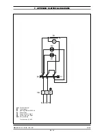
Страница 19: ...9 20 04 2008 7 APPENDIX ELECTRICAL DIAGRAMS mA N L1 PE B1 1 2 3 H1 H2 R1 F1 MV mA B1 R1 F1 H1 H2 MV Terminal board Commutator Heating element 2500 W Thermostat Green indicator light Yellow indicator light Motorized fan Total power 2 5 kW ...

Страница 20: ... PRINTING ERRORS DUE TO ITS POLICY OF CONTINUAL PRODUCT IMPROVEMENT THE MANUFACTURER RESERVES THE RIGHT TO MAKE ANY CHANGES DEEMED NECESSARY THE MANUFACTURER CANNOT BE HELD RESPONSIBLE IF THE INSTRUCTIONS CONTAINED IN THIS MANUAL ARE NOT OBSERVED WHIRLPOOL EUROPE srl V le Guido Borghi 27 I 21025 Comerio VA ...

Отзывы: