


24
SinterPro
Furnace Operator’s Manual
Replacement Of Logic PCB
WARNING: BEFORE ATTEMPTING ANY OF THE SERVICE
PROCEDURES IN THIS SECTION BE SURE TO TURN
OFF THE OVEN POWER VIA THE POWER SWITCH AND
DISCONNECT THE OVEN FROM THE WALL POWER.
Logic PCB Replacement
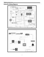
Refer back to the System Wiring Diagram on page 25 for
wiring cable references. The “W” number of the cable
shows where both ends connect.
1. Remove all Power from the oven.
2. Rotate the oven so that you have access to the lower
rear chassis panel.
3. Remove the lower rear panel with a Philips head
screwdriver.
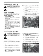
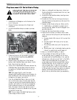
4. Tag all the electrical wiring to match the photograph
above so that you know where to replace the cables.
5. Remove the four hex nuts affixing the logic PCB to the
inside of the chassis.
6. Gently remove the PCB from the studs and set aside.
7. Place the new logic board back onto the same studs,
replace the hex nuts, and tighten.
8. Re-install the cables.
9. Power up the oven and verify the Power On Self-Test
executes properly as below;
a. The green Heater LED comes on for 1 second, then
goes off.
b. The yellow Alarm1 LED comes on for 1 second,
then goes off.
c. The red Alarm2 LED come on for 1 second, then
goes off.
d. The distinctive “click” of the Muffle Safety contactor
is heard 1 second after the red LED goes off.
Replacement Of Alarm PCB
WARNING: BEFORE ATTEMPTING ANY OF THE SERVICE
PROCEDURES IN THIS SECTION BE SURE TO TURN
OFF THE OVEN POWER VIA THE POWER SWITCH AND
DISCONNECT THE OVEN FROM THE WALL POWER.
Alarm PCB Replacement
Refer back to the System Wiring Diagram on the page 25
for wiring cable references. The “W” number of the cable
shows where both ends connect.
1. Remove all Power from the oven.
2. Remove the lower rear panel with a Philips head
screwdriver.
3. Remove the four hex nuts affixing the alarm PCB to the
inside of the chassis.
4. Gently remove the PCB from the studs, and set aside.
5. Place the new Alarm board back onto the same studs,
replace the hex nuts, tighten.
6. Re-install the cables.
7. Power up the oven and verify the Power On Self-Test
executes properly as below;
a. The green Heater LED comes on for 1 second, then
goes off.
b. The yellow Alarm1 LED comes on for 1 second,
then goes off.
c. The red Alarm2 LED come on for 1 second, then
goes off.
d. The distinctive “thump” of the Muffle Safety contac-
tor is heard 1 second after the red LED goes off.


