22
SinterPro
Furnace Operator’s Manual
Replacement Of Heating Elements
WARNING: BEFORE ATTEMPTING ANY OF THE SERVICE
PROCEDURES IN THIS SECTION, BE SURE TO TURN
OFF THE OVEN POWER SWITCH AND DISCONNECT
THE OVEN FROM THE WALL POWER, OR LOCKOUT
AND TAG THE WALL CIRCUIT BREAKER SO THE OVEN
CANNOT BE POWERED DURING THE SERVICING.
1. Lower the lift platform to the fully down position.
2. Remove all Mains Power from the oven, and unplug the
Mains Power cord for safety.
3. Remove the top panel with a Philips head screwdriver.
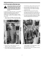
4. Two 7/16” box end wrenches are required to remove
the bolts fastening the Heater Element electrical straps.
5. Unplug the two leads connecting the heater wires to
the square white panel on the chassis by grasping
them and gently pulling towards the front of the oven.
They will slide about an inch before disengaging.
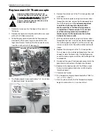
6. Remove all six (6) 7/16” bolts interconnecting the
four heater elements. This will require a second 7/16”
wrench on the underside to provide resistance against
the wrench on the upper side.
CAUTION: Do not allow the wrenches to rotate such
that undue strain is placed on the Heating Element,
especially when installing the new Heating Elements.
7. Once the bolts have been removed, and each individual
element is free, grasp the white ceramic insulator and
begin raising the Heating Element vertically out of the
roof of the Muffle. Take care not to tilt the element off of
vertical or the insulation may chip away.
8. Withdraw all four elements and set them aside.
9. Unwrap all four of the replacement elements.
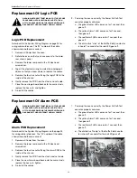
10. CAREFULLY lower each element into the hole in the
roof of the Muffle.
CAUTION: UNDER NO CIRCUMSTANCES ATTEMPT TO
ENERGIZE THE MUFFLE WITH ANY OF THE ELEMENTS
NOT INSERTED FULLY!
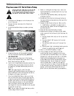
11. After the four elements have been inserted and seated
fully, replace the electrical hardware you removed in
step number 5. Make sure there is a
LOCK WASHER
BETWEEN THE STRAPS
, then place a lock-washer
on the bolt, then the nut, and tighten securely, taking
care not to twist the elements by tugging on the
electrical straps. Make the connections between the
middle element and the end elements first, then finish
with attaching the end element straps.
Plug the two
electrical pins back into the jacks on the chassis
and push them all the way in.
12. Form the loops of the straps with your fingers away
from the center of the ends so that there is maximum
clearance between the straps. Check to make sure
there are no loose strands bridging the two straps.
13. Re-mount the top cover.
14. Power the Oven on.
15. Verify that the Power On Self-Test sequence executed
correctly.
a. The green Heater LED comes on for 1 second, then
goes off.
b. The yellow Alarm1 LED comes on for 1 second,
then goes off.
c. The red Alarm2 LED come on for 1 second, then
goes off.
d. The distinctive “thump” of the Muffle Safety
contactor is heard 1 second after the red LED
goes off.
16. Run a test cycle without anything in the Muffle to verify
normal operation. You may detect an odor during the
first cycle which is due to the new Heater Elements
“breaking-in”. The odor should be gone by the second
or third cycle, and will not return.
NOTE:
CLEAR, THIN, GLASS “SOAP BUBBLES” MAY
APPEAR ON THE HEATING ELEMENTS FOR THE FIRST
FEW WEEKS OF OPERATION. THIS IS AN ENTIRELY
NORMAL AND EXPECTED PHENOMENON RESULTING
FROM OXIDATION OF THE SILICON CARBIDE ELEMENTS.
THE BUBBLES RESULT FROM SMALL QUANTITIES OF
CARBON DIOXIDE GAS WHICH IS NON-TOXIC AND NON-
REACTIVE WITH ZIRCONIA.
NOTE:
You may get a “rotten egg” smell and even notice a
slight bit of grey smoke the first time the heaters are fired.
This is NORMAL, and will disappear after the first firing. It is
recommended that you run a complete sintering cycle with
nothing in the muffle to allow the heater rods to outgas fully.

