background image

19

SinterPro

 Furnace Operator’s Manual 

Routine Maintenance

Cleaning Instructions

It is the user’s responsibility not to use decontamination 
or cleaning agents that could cause a hazard as a result 
of a reaction with parts of the equipment or with material 
contained in it. In order to be sure that such a reaction 
will not occur, we recommend using only a damp cloth 
moistened with water to clean the furnace. Never clean the 

display window with a dry cloth or tissue. Always moisten 
the cleaning cloth with water before wiping the screen.  
Note: If hazardous material is spilled on or inside the 
furnace, contact Whip Mix Technical Support if there is any 
doubt how to safely remove the material.

Power Failure

1.  If a power failure occurs, the SinterPro memorizes 

the conditions prior to the loss of power. When power 
returns, the SinterPro returns to the same point in the 
program.

2.  When power is returned, the 

HR:MIN light flashes


indicating that a power failure has occurred. 

It 

continues to flash until START / STOP is pressed.

NOTE:

 The HR:MIN light flashes if the power switch 

is turned off and on while a program is running and 
START / STOP was not pressed. It will not flash if the power 
switch was turned off or a power failure occurred when the 
PROGRAM READY light was on.

Service

CAUTION:

 The SinterPro Sintering Furnace should be 

serviced only by qualified service technicians. Be sure to 
unplug the power cord and wait for the furnace to cool 
before performing any service operation. For help with 
operating or servicing your Whip Mix equipment, please 

call Whip Mix any time between 8:00 a.m. and 5:00 p.m. 
Eastern time.

Toll Free 1–800–626–5651 
Local 1–502–637–1451 
FAX 1–502–634–4512

Fan Filter Cleaning (Weekly)

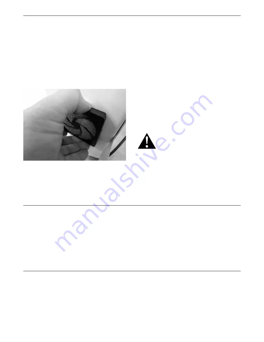
Carefully remove the filter guard by unsnapping the guard to 
gain access to the cellular foam filter.  Rinse the filter clean 
and dry it by blotting it on a paper towel.  Slip the filter foam 
back inside the guard and press the guard back in place.

An alternative method is to vacuum the filter in place with 
the nozzle of a hand vacuum or shop vac.

An Er10 error code indicates the fan filter is clogged and 
the fan has slowed measurably.  This error is a reminder 
to clean the filter and will not preclude operation but it 
will not stop showing up until full fan speed is restored.

An Er11 error code indicates the fan has stopped 
turning.  This error will inhibit further use of the oven 
until the cause is remedied.

CAUTION: DO NOT ALLOW THE FILTER TO BECOME 
CLOGGED WITH DUST OR THE CIRCUIT BREAKER CAN 
TRIP DUE TO THERMAL OVERLOAD. DO NOT DISCARD 
THE FILTER OR DUST CAN ENTER THE ELECTRONICS 
AND DAMAGE THEM.

Содержание SinterPro

Страница 1: ...SinterPro Operator s Manual Whip Mix Corporation 361 Farmington Ave P O Box 17183 Louisville KY 40217 0183 USA 502 637 1451 800 626 5651 Fax 502 634 4512 www whipmix com ...

Страница 2: ...age Program 12 Sample One Stage Program 12 Running a Program 12 To Program And Operate Two Stage Program 13 Sample One Stage Program 13 Running a Program 13 To Program And Operate Three Stage Program 14 Sample One Stage Program 14 Running a Program 14 To Program And Operate Four Stage Program 15 Running a Program 15 To Review A Program 15 Edit A Program While The Program Is Running 16 Purging The ...

Страница 3: ...objects greater than 12 5mm no liquid protection Introduction Thank you for purchasing a SinterPro Sintering Furnace We have designed and manufactured this furnace using the latest in microcomputer technology to give you many years of dependable service To ensure that your SinterPro Sintering Furnace gives you the highest level of service review and follow the guidelines outlined in this Operator ...

Страница 4: ...DANGEROUS COMPONENTS FAILURE TO HEED THIS WARNING MAY RESULT IN EQUIPMENT DAMAGE PERSONAL INJURY AND OR DEATH CAUTION THE TEMPERATURE DISPLAYED IS ACCURATE ABOVE 70 C 158 F NEVER INSERT OR RETRIEVE WORK WITH A BARE HAND ALWAYS USE THE SINTERING TRAY PLACEMENT TOOL TO INSERT OR RETRIEVE SINTERING TRAYS OR BURNS MAY RESULT NOTE CLEAR THIN GLASS SOAP BUBBLES WILL APPEAR ON THE HEATER ELEMENTS THIS IS...

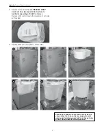
Страница 5: ...ASIER TO PERFORM WHEN THE TOP OF THE MUFFLE IS AT WAIST HEIGHT WHILE ON THE SHIPPING PALLET 4 Remove carton lid and locate READ ME FIRST document to review important instructions to familiarize unpacking of SinterPro furnace Remove white metal lid and other documents set aside until needed 5 Remove black cut foam spacers outer carton 1 2 5 3 6 4 ...

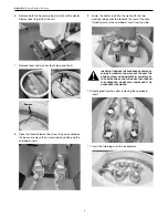
Страница 6: ...sert 9 Lower the heater rods into the wells with the two electrical plugs oriented towards the rear of the oven Carefully remove the cardboard insert from the side IMPORTANT REMOVE THE CARDBOARD CARRIER BY SLIDING IT SIDEWAYS YOU MAY HAVE TO GRASP THE BRAIDED STRAPS AND MOMENTARILY RAISE TWO OF THE HEATER RODS A COUPLE INCHES TO WITHDRAW THE CARDBOARD DO NOT APPLY POWER UNTIL THE CARDBOARD IS REMO...

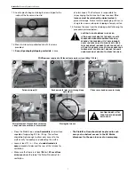
Страница 7: ...YOUR BACK PLACE THE LOOP OVER YOUR FOREARM UP TO THE ELBOW THEN USE THE SAME HAND PLACED ON THE OVEN TO STEADY THE LOAD Place the SinterPro on a non flammable level surface capable of supporting 200 lb 90 kg The surface should be high enough to allow easy access to the muffle cavity for loading and unloading the muffle Leave at least 12 in 31cm of unobstructed air space around all sides and the re...

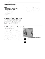
Страница 8: ...upply wire size accounts for the distance from the power source to the oven outlet The maximum impedance of the power supply to the furnace must be less than 0 032 ohms as determined by licensed electrician Back Panel Component Familiarization 1 Mains Power Circuit Breaker 2 3 AMP Control Logic Circuit Breakers 2 3 Mains Power Cord Power The On Off power switch is also a circuit breaker The switch...

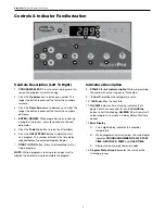
Страница 9: ...begins 7 START STOP button Press to immediately start or stop a program NOTE While a program is running press delay start to display the time remaining to complete the program Indicators Description 8 STAGE 1 2 3 4 indicator lights While programming the number of active stages are illuminated 9 F and C identifies the temperature scale 10 MIN identifies the heat rate 11 HH MM indicates time Flashin...

Страница 10: ...e degree light switches to the opposite temperature scale and the displayed value switches to those units To Turn The Beep On And Off When a program is completed 20 beeps sound every 15 minutes to inform the operator that the Sintering cycle is completed 1 Be sure the oven is in the Standby MODE no program us running 2 Press the Up Arrow key and PROGRAM SELECT simultaneously to display the status ...

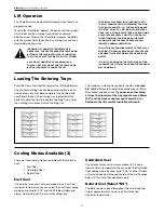
Страница 11: ...LL COMMENCE Loading The Sintering Trays Press the Down Arrow button to lower the lift firing platform One shallow sintering tray one deep sintering tray one lid and a zirconia tray liner bead sample jar are included with your SinterPro oven The sintering tray is indented at the bottom to allow the tray to index into the firing tray to hold the sintering tray concentric with the firing tray The max...

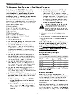
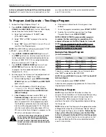
Страница 12: ...t turns off STAGE 2 and HEAT RATE lights turn on B Press either Arrow key Main Display shows 5 4 3 2 1 COOL NO Select NO to program the furnace for a one stage cycle NO Natural Cooling C If Fast Cooling is desired scroll to FCL or if Controlled Cooling is desired scroll to CCL instead of NO This will allow natural cooling down to around 900 C then progressively lower the lift platform automaticall...

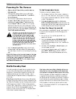
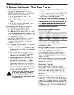
Страница 13: ...t stage of a program so the NO entry is not required in this case CAUTION THE TABLE WILL AUTOMATICALLY LOWER VERY SLOWLY BE ADVISED THAT THE MATERIAL TRAYS AND THE LIFT PLATFORM INSULATION ARE TOO HOT TO SAFELY TOUCH WITH YOUR HAND USE FORCEPS AND INSULATED GLOVES WHEN HANDLING THE SINTERING TRAYS 6 All necessary information for this program is now entered 7 To run the program immediately press ST...

Страница 14: ...NDLING THE SINTERING TRAYS 6 All necessary information for this program is now entered 7 To run the program immediately press START STOP 8 To delay the start of the program see One Stage Program Step 3 press DELAY START NOTE If DELAY START key is pressed while a program is running the time remaining for completion of the program will appear on the Main Display for 5 seconds NOTE It is recommended ...

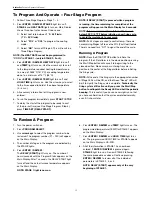
Страница 15: ...TE Press the START STOP button to initiate the program If the Lift platform is in the down position pressing the Start Stop button will cause it to begin rising to the closed position Make sure your sintering trays are in position in the center of the firing platform before initiating the firing cycle NOTE At the end of the firing cycle the appropriate number of Stage LEDs will be ON and the Green...

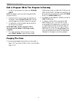
Страница 16: ...EW to advance to the desired STAGE and parameter i e HEAT RATE TEMP or HOLD TIME Initially STAGE 1 will appear Any parameter can be increased or decreased by pressing the UP ARROW button or the DOWN ARROW button 5 Any program can be stopped or started by pressing the START STOP button 6 If a program is edited while running and the HEAT RATE in STAGE 2 3 or 4 is set to COOL but the corresponding TE...

Страница 17: ...r turned on Button circuit breakers on back panel are pushed in Check the building power source for tripped circuit breaker Turn oven power switch off then on again Main Circuit Breaker Trips when program running Fan filter clogged fan not running fan in base of column Clean fan filter insure fan running Hood Temperature uncomfortably hot to the touch Upper fans 2 one or both not turning Call for ...

Страница 18: ...es have been connected backwards to the terminals on the printed circuit board Er7 THERMAL RUNAWAY Occurs when the temperature has exceeded 1600 C 2912 F instantly or exceeded 1585 C 2885 F for 1 minute Er8 High Temperature Thermocouple failure Replace Thermocouple Er9 Cavity Temperature Stall Heaters have reached end of useful life replace all 4 heater rods Er10 Check Clean Cooling Fan Reminder A...

Страница 19: ...or a power failure occurred when the PROGRAM READY light was on Service CAUTION The SinterPro Sintering Furnace should be serviced only by qualified service technicians Be sure to unplug the power cord and wait for the furnace to cool before performing any service operation For help with operating or servicing your Whip Mix equipment please call Whip Mix any time between 8 00 a m and 5 00 p m East...

Страница 20: ... the oven and unplug the mains power cord for safety 2 Rotate the furnace so that the back of the chassis is facing you and leave sufficient space for the bottom rear panel to lay flat 3 Remove the rear top cover panel with a phillips screwdriver leaving the third row of screws one on each side from the top intact The third row of screws need not be removed to remove the top cover panel 4 Then rem...

Страница 21: ...oop Then locate the remaining holes of the shield to the corresponding studs with downward pressure on the shield for ease of assembly Ensure the electrical wire connections are not disturbed 11 Secure the shield with nuts using the nut driver 12 Replace the rear bottom cover panel first ensuring all the wires are inside the unit without any risk of pinching the wires while securing the panel with...

Страница 22: ...eated fully replace the electrical hardware you removed in step number 5 Make sure there is a LOCK WASHER BETWEEN THE STRAPS then place a lock washer on the bolt then the nut and tighten securely taking care not to twist the elements by tugging on the electrical straps Make the connections between the middle element and the end elements first then finish with attaching the end element straps Plug ...

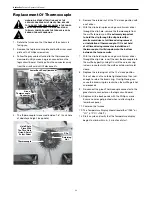
Страница 23: ...he clip hole remove the thermocouple from the muffle towards you It is extremely important to hold the clip through the clip hole with a small screw driver at all times during removal or installation of thermocouple If it is not held at all times during removal or installation of thermocouple it will drop down to the bottom between the furnace walls 7 With the clip held in place using a small scre...

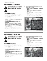
Страница 24: ... yellow Alarm1 LED comes on for 1 second then goes off c The red Alarm2 LED come on for 1 second then goes off d The distinctive click of the Muffle Safety contactor is heard 1 second after the red LED goes off Replacement Of Alarm PCB WARNING BEFORE ATTEMPTING ANY OF THE SERVICE PROCEDURES IN THIS SECTION BE SURE TO TURN OFF THE OVEN POWER VIA THE POWER SWITCH AND DISCONNECT THE OVEN FROM THE WAL...

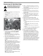
Страница 25: ...e Solid State Relay and the white coating will hold it in place 8 Before re installing the mounting screws make sure the Solid State Relay is oriented exactly the way it was in the photo above 9 Re install the two Solid State Relay mounting screws and tighten securely 10 Re connect all the wires by matching up the tags on the wires with the marking numbers on the face of the Solid State Relay 11 R...

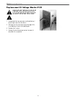
Страница 26: ...F THE OVEN POWER VIA THE POWER SWITCH AND DISCONNECT THE OVEN FROM THE WALL POWER 1 Remove both the top rear panel and the bottom rear panel to gain access to the chassis 2 Disconnect all the connectors along the edge of the circuit board as shown in the photo below 3 Remove the 2 screws 4 Remove the circuit board and reverse the order of operations to re assemble ...

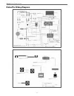
Страница 27: ...27 SinterPro Furnace Operator s Manual SinterPro Wiring Diagram ...

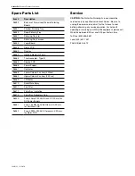
Страница 28: ...Solid State Relay 96571 Fan Filter 96572 Firing Tray Insulation 96573 Firing Tray Refractory Cap 96540 Fuse 4Amp 250 Volt Glass 5 X 20 mm for DC Power Supply 96541 Fuse 125 MA 250 Volt Glass 5 X 20 mm for Volt Mon PCB 96542 Fuse 50 MA 250 Volt Ceramic 5 X 20 mm for Alarm PCB Service CAUTION The SinterPro Sintering Furnace should be serviced only by qualified service technicians Be sure to unplug t...

Отзывы: