background image

page  3 – 8

L-8 / Sep 2013

L - 8   C O N T R O L S   A N D   F U N C T I O N S

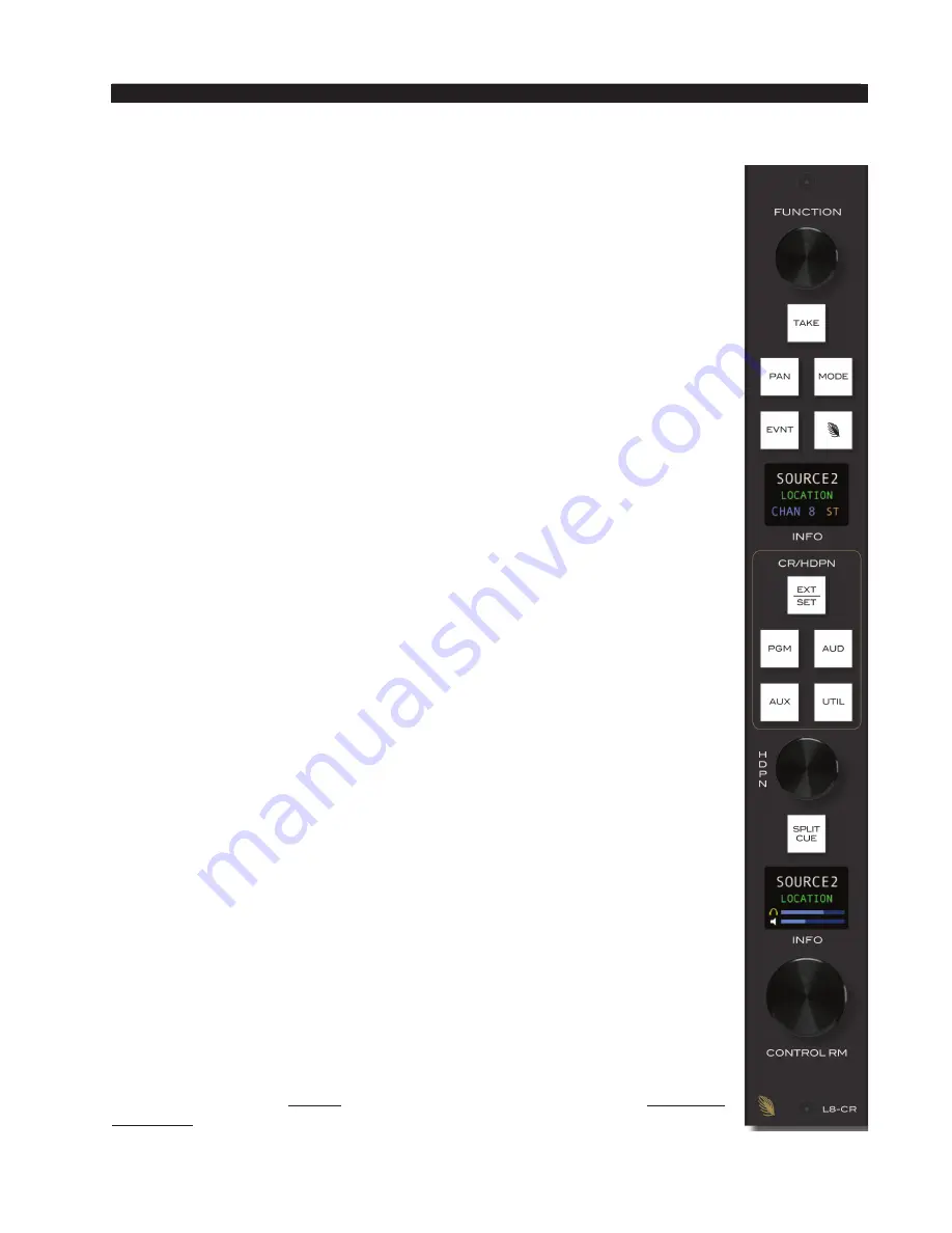
Source Select Switches

The bank of source select switches in the center of the L8‑CR module 

selects the audio signal sent to the speakers and the headphones. This bank 

includes dedicated switches for selecting PGM (program), AUD (audition), 

AUX (auxiliary), or UTIL (utility), and a programmable EXT source. Simply 

press the desired switch to listen to that output bus or external source signal. 

The button will be lit when the monitor is assigned to its respective bus, and the   

bottom display will show the source name. Adjust the volume of the head‑

phones and speakers by rotating the HDPN and CONTROL RM level con

trols respectively.

Programming External Source Switch

The external switch may be programmed to select any allowed source in 

the system. Press and hold the EXT/SET button until it begins to flash, then 

rotate the FUNCTION knob until the desired source appears in the module’s 

top display, then press TAKE (which is also lit) to finish programming the 

button.

Depending on how the L‑8 is configured, you may be able to select any 

source in the system or you may have a limited choice of sources for the 

external switches.

CONTROL RM Level Control

The CONTROL RM level control determines the overall loudness of the 

signal being monitored (PGM, AUD, AUX, UTIL, or EXT) as it appears in 

the Control Room speakers. As the control is turned clockwise, the loudness 

increases. To decrease the loudness, turn the control in a counterclockwise 

direction. 

The bottom display shows the source name and location of the monitored 

source, and two horizontal lines. The bottom line indicates the volume level 

for the control room speaker. 

The L‑8 may be configured so that this level control has no effect by 

locking the Control Room outputs on the Monitor Config tab of the 

Wheatnet 

IP L8 Setup Tool

 GUI.

NOTE: If the Control Room is muted and you turn the level control all 

the way up, then remove the condition that has the Control Room muted, 

the sound in the Control Room speakers will suddenly be VERY LOUD!

HEADPHONE Level Control

The HDPN level control determines the overall loudness of the headphone 

output signal, which monitors the same source (PGM, AUD, AUX, UTIL, 

or EXT) as the Control Room speakers.

The headphone output signal appears at the HEADPHONE JACK, located 

on the right side of the control surface. The jack is provided as a place to 

plug in user‑supplied 

stereo

 headphones having an impedance of 

60 Ohms 

or higher

.

Содержание L-8

Страница 1: ...L 8 600 Industrial Drive New Bern North Carolina USA 28562 Modular Control Surface TECHNICAL MANUAL ...

Страница 2: ...WHEATSTONE CORPORATION 600 Industrial Drive New Bern North Carolina 28562 tel 252 638 7000 fax 252 637 1285 L 8 Modular Control Surface Technical Manual 2013 Wheatstone Corporation L 8 Sep 2013 ...

Страница 3: ... supply see next page for details Other then the physical dimensions and two extra slots for the Accessory panels all other aspects of the L 12 are the same as the L 8 The L 12 audio control surface is designed for countertop placement The rubber feet on the bottom keep the surface from being easily moved when simply placed on the counter 25 5 8 25 1 8 16 1 8 3 7 8 1 1 2 25 1 8 24 1 8 2 3 8 ...

Страница 4: ...d Ethernet connectors are mounted on the Host Controller card HC L8 PCB located behind the control surface s rear panel Unscrew the rear panel to make power and Ethernet connections The power jack at the left of the HC L8 PCB is for the power connection The factory supplied power cable has coaxial power jacks on the both ends to connect the L 12 to the PSE L DC OUT connector The RJ 45 connector on...

Страница 5: ...olated AC ground outlet It is usually orange in color Energizing Assuming the L 12 control surface mainframe is properly placed and its PSE L power supply correctly rackmounted and connected to the control surface you may now energize the rackmount power supply by plugging it into the AC mains The power supply s front panel green POWER LED should light up to indicate that the power supply is on Th...

Страница 6: ...third prong are provided for your safety If the provided plug does not fit into your outlet consult an electrician for replacement of the obsolete outlet 10 Protectthepowercordfrombeingwalkedonorpinchedparticularlyatplugs convenience receptacles and the point where they exit from the apparatus 11 Only use attachments accessories specified by the manufacturer 12 Unplug this apparatus during lightni...

Страница 7: ...rnie pour votre sécurité Si la fiche fournie ne rentre pas dans votre prise consultez un électricien pour le remplacement de la prise obsolète 10 Protéger le cordon d alimentation en évitant qu il ne soit piétiné ou écrasé notamment au niveau des fiches et le point de sortie de l appareil 11 N utiliser que les fixations et accessoires spécifiés par le fabricant 12 Débrancher cet appareil pendant l...

Страница 8: ...f not installed and used in accordance with the instruction manual may cause harmful interference to radio communications Operation of this equipment in a residential area is likely to cause harmful interference in which case the user will be required to correct the interference at his own expense This is a Class A product In a domestic environment this product may cause radio interference in whic...

Страница 9: ...before you start Launch the Navigator GUI and make sure that System 0 is selected in the System pane You will see something like this Now select the Peripheral Devices tab Click the Add button to bring up the Add Peripheral Device dialog Type in a convenient Name and insert the IP Address of the device being added Leave the TCP Port at the default setting of 60021 From the Host BLADE drop down sel...

Страница 10: ...nfo Tab 2 4 Engine Tab 2 6 Talent Access Tab 2 8 VDips Tab 2 10 Monitor Config Tab 2 13 Buttons Tab 2 14 Visibilities Tab 2 15 GUI Menu Summary 2 16 Control Surface Menus 2 17 Network 2 17 Blade 2 17 Versions 2 17 Exit Menu 2 18 Input Module L8 IN 3 2 Input Sources 3 2 Soft Button 3 3 Assign Switches 3 3 The UTIL Bus 3 3 Display 3 3 TB Switch 3 4 CUE Switch 3 4 Bus Minus Direct Outputs 3 4 Fader 3...

Страница 11: ... 3 11 VU Meter Pairs 3 11 METER Select Button 3 12 Time of Day 3 12 TIMER Buttons 3 12 General Information 4 2 Installation Tips 4 2 Energizing 4 4 I O Connections 4 5 Inputs 4 5 Outputs 4 7 Logic Ports 4 8 Console BLADE3 88cbl Input Output Pinout Drawing 4 9 Front Panel Metering 4 10 Front Panel Dual OLED s 4 10 BLADE3 Setup Mode 4 11 BLADE3 Front Panel Configuration 4 13 Front Panel Menu Diagram...

Страница 12: ...page Contents 3 L 8 Sep 2013 C O N T E N T S Appendices Appendix 1 Appendix 2 Replacement Parts List A 3 Configuring L 8 for Use in WheatNet IP Systems A 6 L 8 Dec 2016 ...

Страница 13: ...page 1 1 L 8 Sep 2013 G E N E R A L I N F O R M A T I O N Chapter Contents General Information Introduction 1 2 Control Surface Placement 1 3 Power Supply and Ethernet Connections 1 4 ...

Страница 14: ... Audio Over IP Network Technical Manual for information on configuring your system and for descriptions of the various types of BLADEs and the Windows XP Navigator GUI The meterbridge features three sets of bright ultra high resolution LED meters A digital timer is also included The L 8 has control room and headphone outputs with level control and source selection as well as an independent studio ...

Страница 15: ...p place ment The L 8 is a sleek versatile and low profile control surface Avoid proximity to any electromagnetic fields such as large power transformers motors and fluorescent lighting fixtures NOTE This console contains static sensi tive devices Normal precautions against staticdischargeshould be observed 16 1 8 16 5 8 2 3 8 4 16 1 4 1 1 2 ...

Страница 16: ...akepowerandEthernetconnections The power jack at the left of the HC L8 PCB is for the power connection The factory supplied power cable has coaxial power jacks on the both ends to connect the L 8 to the WheatNet IP 88cbl Console BLADE DC OUT connector TheRJ 45connectorontherightpartoftheHC L8PCBprovides control surface connection to a standard Ethernet network switch via a straight pin to pin CAT5...

Страница 17: ...nfiguration Getting Started 2 2 Tabbed Navigation 2 3 System Info Tab 2 4 Engine Tab 2 6 Talent Access Tab 2 8 VDips Tab 2 10 Monitor Config Tab 2 13 Buttons Tab 2 14 Visibilities Tab 2 15 GUI Menu Summary 2 16 Control Surface Menus 2 17 Network 2 17 Blade 2 17 Versions 2 17 Exit Menu 2 18 ...

Страница 18: ... may be located either next to the control surface or at a remote location The L 8 control surface comes with the Wheatnet IP L8 Setup Tool Graphical User Interface GUI program intended to be straightforward in setup connection between the control surface and the Console BLADE3 On a user supplied computer connected through an Ethernet switch to the L 8 and the Console BLADE3 install the GUI by run...

Страница 19: ...evice to the list Edit to change the name of an L 8 or give the GUI a different IP address to talk to it on or Remove to delete the device currently highlighted in the list To the right of these buttons is the Online check box which is used to toggle the GUI connection to the highlighted device between online checked and offline not checked The Function Pane contents change according to the tab se...

Страница 20: ...u This will display the WheatNet IP System Scan screen Start by specifying the Host Blade IP Address This can be the IP address of any physical BLADE inthesystem Next clickStartScan Whenthescan is complete you will see a screen like this the exact text is system dependent ClickFinish Youwillbeaskedifyouwant to save the System Info If you click Yes you will be prompted for the location and name of ...

Страница 21: ...program for special functions and we may choose also to limit source visibility for input channels You will need to do the system scan before performing these operations It is important to note that Blade Picker and Source Picker functions will use the last scan information you saved If you have changed configuration in regard to Blades present or signals defined and their names since last saving ...

Страница 22: ...annel can be turned ON or OFF by a surface action such as pressing the ON or OFF switch or moving a fader if EFS has been enabled Remote RMT A channel can be turned ON or OFF by sending it a command from a system Logic I O card via the RemOn and RemOff functions When the No LIO with RMT check box is checked LIO signals are globally blocked for all input faders if the channel ON and OFF commands ar...

Страница 23: ...the display The possible values vary from a low of 1 off to a high of 16 AutoDim Level This control specifies the brightness level to be used when the displays are in screen saver mode The possible values vary from a low of 1 off to a high of 16 AutoDim Timeout This control specifies how long in minutes to wait before entering screen saver mode The Control Surface controls must be idle before en t...

Страница 24: ... operator will not be able to use MODE button to switch the channel s mode Event Names Shows the list of available events Names will default to Event 1 Event 2 etc if not edited here X Controllers Selection of fader sources by using the A B input button on the L8 IN Input Module can be limited as follows If Allow Program A B Buttons is not checked the operator will not be able to program the A B b...

Страница 25: ...us to the AUD bus If Allow AUX Bus Assign is not checked the operator will not be able to use the AUX ASSIGN button to change any fader s feed status to the AUX bus If Allow OL Bus Assign is not checked the operator will not be able to use the UTIL ASSIGN button to change any fader s feed status to the UTIL bus ...

Страница 26: ...es in the system except those you have specifically overridden If you want to edit the VDip settings of a specific signal to be different than the default settings you first need to add the signal to the Signals list Click the Add button to bring up the Add Signal dialog Click the button with the three dots ellipsis to the right of the Source Signal field to bring up the Source Picker dialog NOTE ...

Страница 27: ...right click and select Paste This copies the VDip settings from the first signal to the second one Please note that all VDip settings apply to the programmed signal regardless of which fader the signal appears on PFL Cue Dropout When a channel s CUE button is pressed it will assign the channel s signal to the CUE bus When PFL Cue Dropout is checked it causes the channel sCUEfunctiontobede activate...

Страница 28: ...k boxes one for each monitor section plus one for CUE The checked boxes show which monitors are muted Studio Tallies Turning the channel ON can activate a remote tally indicator There are four tally control lines The checked boxes show which tallies are activated This requires additional configuration in the optional Navigator GUI to fully implement the feature Also note that the Studio Tallies se...

Страница 29: ...dio monitor as an example adjust the STUDIO level control on the L8 SC to the desired level thenchecktheLevelLockedbox in the Studio section of the Monitor Config tab The monitor output will remain at the fixed level regardless of any changes in the STUDIO level control position If at a later time you decide to unlock the level the level will still be unchanged until the next time the STUDIO knob ...

Страница 30: ...odethebuttonactslikeatoggle with one press turning it on and the next press turning it off the button is illuminated by the surfacewhenintheonstateandisnotilluminated in the off state Momentary Surface LED in this mode the button has a momentary action on while pressed and off when released the button s illumination is controlled by the surface being lit while the button is pressed Momentary LIO L...

Страница 31: ...box to sort the list of channels in alphanumeric order when selecting sources on the L 8 Check Allow No Source if you want NoSource to be allowed for that channel If NoSource is not allowed then the channel must always have a source selected Right clicking in the Channel area of the Visibilities tab pops up a menu with some useful shortcuts on it Copy Choose this item to copy the visibility settin...

Страница 32: ...he L 8 GUI is connected to get a list of all signals currently available in the system see page 2 4 this set can then be saved using File Save and then later recalled using File Open even if the L 8 is not connected to the system at that time Hardware The Hardware menu is used to set up devices in respect to connecting to them and managing their configuration and software Add New Device Used to se...

Страница 33: ...dress dobby the FUNCTION knob and you can edit the IP address Netmask this item allows you to view the subnet mask for the L 8 dobby the FUNCTION knob to edit the subnet mask Gateway this item allows you to view the gateway setting for the L 8 dobby the FUNCTION knob to edit the gateway MAC Address this item allows you to view the MAC address for the L 8 note that you cannot edit the MAC address B...

Страница 34: ...nu Turning the FUNCTION knob until Exit Menu is highlighted and dobbying the FUNCTION knob exits from the control surface menu If you have the menu dis played and are idle not turning or pressing anything for about 20 seconds the L 8 will automatically exit from the menu ...

Страница 35: ...om Module L8 CR 3 6 Displays 3 6 FUNCTION Knob 3 6 PAN Control 3 6 MODE Button 3 7 Event 3 7 Source Select Switches 3 8 Programming External Source Switch 3 8 CONTROL RM Level Control 3 8 HEADPHONE Level Control 3 8 SPLIT CUE Button 3 9 System Information 3 9 Studio Control Module L8 SC 3 10 Displays 3 10 Source Select Switches 3 10 Programming External Source Switch 3 10 CUE Level Control 3 10 ST...

Страница 36: ...Once the A and B sources have been programmed you can easily switch between them by momentarily pressing the A B SET switch Since it may be desirable on occasion to assign a source to a channel other than its two programmed A and B sources we also allow selecting a third source also called a Wild Card to the channel without needing to reprogram the A or B source The procedure is quite similar to t...

Страница 37: ...pecify which bus PGM AUD AUX or UTIL provides the base Bus Minus mix that is which bus the Bus Minus output is a mix minus of when that channel is on When the channel is off however the base Bus Minus mix may be the same as when the channel is on or may be configured to utilize the UTIL bus instead This allows the Bus Minus output to have different content when the channel is off than it does when...

Страница 38: ...ot need to be turned ON To remove a fader from cue press the CUE button again the light will go off to indicate the channel is no longer assigned to cue Bus Minus Direct Outputs EachfaderhasadedicatedBus Minusoutputthatincludesallactivefaders on its selected source bus except for itself These auto generated monaural Bus Minus signals may be routed to feed telephone hybrids remote operator feeds or...

Страница 39: ...ight on the left upper corner of the meterbridge if so programmed see the discussion of OnAir tallies in Chapter 2 s Engine Tab section Channel OFF Switch The channel OFF switch turns the channel signal OFF and fires any chan nel OFF STOP logic mapped to the fader s source signal The switch LED lights to indicate the channel is OFF ...

Страница 40: ...instances the control surface operator may also be performing talent whose voice will be heard over the radio The operator s microphone may thus provide a part of the signal that is going out over the air If that signal is the one being monitored with the Control Room speakers there is the potential for feedback The amplified signal from the Control Room speakers is picked up by the microphone and...

Страница 41: ...d holding channel s A B SET button until it begins to flash then pressing the MODE button to cycle through the choices The channel s display will change to reflect the new mode Choose the desired mode and press the A B SET again This operation may be denied to a user in the Talent Access tab of the Wheatnet IP L8 Setup Tool GUI Event The L 8 includes a snapshot save and recall feature that saves a...

Страница 42: ... limited choice of sources for the external switches CONTROL RM Level Control The CONTROL RM level control determines the overall loudness of the signal being monitored PGM AUD AUX UTIL or EXT as it appears in the Control Room speakers As the control is turned clockwise the loudness increases To decrease the loudness turn the control in a counterclockwise direction The bottom display shows the sou...

Страница 43: ...to the right headphone anytime a channel is put into CUE System Information Pressing and holding the CONTROL RM and STUDIO knobs on the bottom of the L8 ST module knobs at the same time for several seconds will cause some configuration information and software version to be displayed in the top display While in this state turning the FUNCTION knob will cycle through the following items The operato...

Страница 44: ...ignal sent to the Studio speakers This bank includes dedicated switches for selecting PGM program AUD audition AUX auxiliary or UTIL utility and a programmable EXT source Simply press the desired switch to listen to that output bus or external source signal The button will be lit when the monitor is assigned to its respective bus Programming External Source Switch The external switch may be progra...

Страница 45: ...es at the bottom The bottom line indicates the volume level for the studio speaker The L 8 may be configured so that this level control has no effect by locking the Studio outputs on the Monitor Config tab of the Wheatnet IP L8 Setup Tool GUI NOTE If the Studio is muted and you turn the level control all the way up then remove the condition that has the Studio muted the sound in the Studio speaker...

Страница 46: ...ime of day is shown in either 12 hour or 24 hour format as set in the Engine tab of the Wheatnet IP L8 Setup Tool GUI The time is obtained from the Host BLADE If no Host BLADE is configured the time starts at midnight when the control surface is powered on TIMER Buttons The control surface timer is provided with an AUTO RESTART function so that input modules can automatically reset the timer displ...

Страница 47: ...tents General Information 4 2 Installation Tips 4 2 Energizing 4 4 I O Connections 4 5 Inputs 4 5 Outputs 4 7 Logic Ports 4 8 Console BLADE3 88cbl Input Output Pinout Drawing 4 9 Front Panel Metering 4 10 Front Panel Dual OLED s 4 10 BLADE3 Setup Mode 4 11 BLADE3 Front Panel Configuration 4 13 Front Panel Menu Diagram 4 15 ...

Страница 48: ...Console BLADE3 because its power consumption is low enough to not require one WARNING Under no circumstances should the WheatNet IPunit be opened Theunitcontainshighvoltagecircuitsthatarehazardousandpotentially harmful The unit has no user serviceable parts inside If you have a problem the unit must be returned to Wheatstone Corporation for repair Installation Tips Place any surge protection circu...

Страница 49: ...ill account for level differences as well as converting between balanced and unbalanced connections For digital audio connections always use a good quality digital audio cable with a characteristic impedance of 110 ohms The AES EBU specification with its broad impedance tolerance allows for cables with impedances from 88 ohms to 132 ohms 110 ohms is ideal Twisted pair cable should be shielded and ...

Страница 50: ...use external surge protection and or an uninterruptible power supply UPS especially where AC power quality is questionable such as at a remote transmitter site Power conditioning surge suppression and even power backup devices are wise investmentswhenusingsensitivemodernelectronicdevicesthatuseaninternalcomputer Use of a UPS uninterruptible power supply is a good idea and will protect the Console ...

Страница 51: ...ich can be individually designated during setup as inputs or outputs These ports are where you wire the various external switches indicators and control functions you need in your facility There are two RJ 45 jacks for Ethernet One is for 1 Gigabit Ethernet connect this one to your network The 100 Megabit Ethernet port is not used do not connect anything to this port Consult the wiring diagram on ...

Страница 52: ...Please note that the sample rate of a digital input 8 should be the same either 44 1kHz or 48kHz as the system s chosen sample rate AES sources are by design stereo if the BLADE is not set to be stereo the appropriate Left or Right signal within the AES stream will be applied to the signal path MIC IN XLR XLR 1 Pin 1 SH XLR 1 Pin 2 HI Mic 1 In XLR 1 Pin 3 LO XLR 2 Pin 1 SH XLR 2 Pin 2 HI Mic 2 In ...

Страница 53: ...O RJ 45 Pin 4 HI RJ 45 Pin 5 LO RJ 45 Pin 7 HI RJ 45 Pin 8 LO STUDIO OUT XLR XLR 1 Pin 1 SH XLR 1 Pin 2 HI Studio Lt Out XLR 1 Pin 3 LO XLR 2 Pin 1 SH XLR 2 Pin 2 HI Studio Rt Out XLR 2 Pin 3 LO CR OUT XLR XLR 1 Pin 1 SH XLR 1 Pin 2 HI CR Lt Out XLR 1 Pin 3 LO XLR 2 Pin 1 SH XLR 2 Pin 2 HI CR Rt Out XLR 2 Pin 3 LO PGM OUT ANALOG RJ 45 RJ 45 A Pin 1 HI RJ 45 A Pin 2 LO RJ 45 A Pin 3 HI RJ 45 A Pin ...

Страница 54: ...45 connectors that provide 12 Universal logic ports LOGIC I O 1 6 RJ 45 RJ 45 Pin 1 Digital Ground RJ 45 Pin 2 Logic 1 In Out RJ 45 Pin 3 Logic 2 In Out RJ 45 Pin 4 Logic 3 In Out RJ 45 Pin 5 Logic 4 In Out RJ 45 Pin 6 Logic 5 In Out RJ 45 Pin 7 Logic 6 In Out RJ 45 Pin 8 5V Digital LOGIC I O 7 12 RJ 45 RJ 45 Pin 1 Digital Ground RJ 45 Pin 2 Logic 7 In Out RJ 45 Pin 3 Logic 8 In Out RJ 45 Pin 4 Lo...

Страница 55: ... LO AES 8 IN HI AES 8 IN LO 1 2 3 4 5 6 7 8 RJ 45 MIC 1 OUT HI MIC 1 OUT LO MIC 2 OUT HI MIC 2 OUT LO MICS OUT 1 2 3 4 5 6 7 8 HDPN LT OUT HI HDPN LT OUT LO HDPN RT OUT HI HDPN RT OUT LO CUE LT OUT HI CUE LT OUT LO CUE RT OUT HI CUE RT OUT LO RJ 45 CUE HDPN OUT 1 3 2 XLR F 1 PIN 1 MIC 1 IN SH PIN 2 MIC 1 IN HI PIN 3 MIC 1 IN LO 1 3 2 XLR F 2 PIN 1 MIC 2 IN SH PIN 2 MIC 2 IN HI PIN 3 MIC 2 IN LO MI...

Страница 56: ...oning as the System Master Clock Master Lights to show that the BLADE 3 is functioning as the system s Clock Master Error Shows an error in network connectivity Front Panel Dual OLED s New BLADE 3s come with dual OLED displays for monitoring and control of most functions right from the front panel including audio routing setup monitoring network information alarm status enabling and operating util...

Страница 57: ...the setup wizard will automatically assign network settings to the BLADE 3 based on your choice of Blade ID For IDs in the range of 1 to 99 IP addresses will be assigned within the 192 168 87 xxx subnet with the last octet being assigned a value of 100 plus the Blade ID The subnet mask will be set to 255 255 0 0 and the gateway will be set to 192 168 87 1 For IDs in the range of 100 to 199 IP addr...

Страница 58: ...d the setup wizard will configure the inputs and outputs of the BLADE 3 as mono signals and add these signals to the system If you choose this template you can later on change some of your signals to stereo if necessary Please note that if you have a lot of mono sources you may be tempted to use this template but you should also consider the rest of your audio equipment you may actually still have...

Страница 59: ...there will be no dots The right window of the Info screens displays whether the BLADE 3 s signal meters are displaying input or output and also shows the BLADE 3 IP Address and Uptime Pressing the left arrow button again will take you back to the screen saver display Clockwise rotation of the knob navigates up and down a menu when there is a list or scrolls thru options in a submenu once one has b...

Страница 60: ...tings can also be edited from this submenu Display Sets the display s brightness and screen saver time Gain Levels Displays the gain levels for selected sources and destinations and allows the user to set the input level for each source and destination Utility Mixer Each BLADE 3 has two Utility Mixers Their features include pan ning channel On OFF fader levels and access to any source signal in th...

Страница 61: ...pe_IP 88m MIC 8 52 0dB MIC 8 OFF Date Time Time_15 16 43 Software_3 2014 REV2 CPU Pri Ext Ref_23 Version Network Hardware_27 20140402 2356 IP Address_192 168 87 111 Subnet Mask_255 255 255 0 Gateway Address_192 168 87 1 Mac Address_40 D8 55 1D 70 DE Change Settings Gateway Address_XXX XX XX XX Mac Address_XXX XXX XXX X IP Address_XXX XXX XX X Reboot No Yes Factory Reset No Yes Sec Ext Ref_2 Displa...

Страница 62: ...ime_09 08 14 15 38 02 Temperature_47 3 C Annc Pkts_9841 Rx 13030358 Annc Errs_Tx 0 Rx 0 LIO Pkts_Tx 0 Rx 231 LIO Errs_Tx 0 Rx 0 GUI_0 Connected Surface_Not available Route Master_No or Yes Clock Master_Yes or No Meters Selected Meters Inputs Outputs Logic LIO Status LIO Out Test Password Change Pasword Gain Levels Sources Destinations Source Gain List Source Gain Levels Destination Gain List Desti...

Страница 63: ... L 8 Sep 2013 H A R D W A R E Host CPU HC L8 Chapter Contents Overview 5 2 Ethernet IP Addressing 5 2 Ethernet Interface Wiring 5 2 Hook Ups 5 3 CT4 RJ 45 Main Ethernet Connector 5 3 Typical Ethernet Cable 5 3 ...

Страница 64: ...tails to the host application running on the HC L8 such as the specific audio hardware available Ethernet IP Addressing The Wheatstone L 8 control surface ships with the host controller IP address set to 192 168 87 201 Stand alone systems not interfaced to a station s existing network require no IP address changes Ethernet Interface Wiring Networked systems are connected to the network hub or swit...

Страница 65: ... C Pin 6 RXD Pin 7 N C Pin 8 N C Typical Ethernet Cable Used for connecting the host controller to your network hub Ethernet Connector RJ 45 1 2 3 4 5 6 7 8 TXD TXD RXD RXD N C N C N C N C 1 2 3 4 TXD TXD RXD RXD PIN 1 2 3 4 PIN RJ 45 Plug RJ 45 Plug White Orange 5 6 7 8 N C N C 5 6 7 8 Orange White Green Blue White Blue Green White Brown Brown N C N C White Orange Orange White Green Blue White Bl...

Страница 66: ...L 8 Dec 2016 A P P E N D I C E S page A 1 Replacement Parts List A 3 Configuring L 8 for Use in WheatNet IP Systems A 6 Appendices Appendix 2 Appendix 1 ...

Страница 67: ...components that in the course of normal use may need maintenance i e faders pots ON OFF switches etc Acomplete list of available components follows Contact Wheatstone technical support for further information Wheatstone Corporation 600 Industrial Drive New Bern North Carolina USA 28562 may be reached by phone at 252 638 7000 fax 252 637 1285 or electronic mail techsupport wheatstone com Contents ...

Страница 68: ...52 FADER KNOB BLACK FADER KNOB 11mm FOR 3000 SERIES FADER 520001 POT KNOB BLACK SOLID ALUMINUM 23MM KNOB NO INDICATOR 6MM SHAFT 520127 POT KNOB BLACK SOLID ALUMINUM 18MM KNOB NO INDICATOR 6MM SHAFT 520131 ENCODER 11MM ROTARY ENCODER WITH THREADED BUSHING 17MM SHAFT LENGTH 560004 ON OFF SWITCH SINGLE POLE MOMENTARY REED KEYBOARD SWITCH 510109 NKK SWITCH JB15 SWITCH W BRIGHTER RED LED AND SILICON GA...

Страница 69: ...T 270067 CONNECTOR RJ 45 SINGLE R A CONNECTOR W GREEN YELLOW LED 220138 HEADPHONE JACK RTS JACK 260005 POWER JACK RIGHT ANGLE 2 5MM CENTER PIN DC POWER JACK 260103 POWER PLUG LOCKING DC POWER PLUG 2 5MM ID 5 5MM OD 260104 ON SWITCH LED 3MM BLUE LED LAMP 600078 OFF SWITCH LED 3MM WHITE LED LAMP 600079 SOURCE DISPLAY 1 27 OLED DISPLAY 610029 MANUAL TECHNICAL MANUAL FOR L 8 CONTROL SURFACE 010399 REP...

Страница 70: ...L 8 Dec 2016 A P P E N D I C E S page A 5 Appendix 2 Configuring L 8 for Use in WheatNet IP Systems A 6 Contents ...

Страница 71: ...eatNet IP engine BLADE3 This BLADE3 must be available and unassociated with any other control surface You can confirm this information via the front panel controls on the engine BLADE3 or from the WheatNet IP Navigator GUI The L 8 control surface comes with the Wheatnet IP L8 Setup Tool Graphical User Interface GUI program intended to be straightforward in setup connection between the control surf...

Страница 72: ...e specific signals created and their default names are a function of the model and size of the associated control surface The following is a listing of a typical set of signals for a XX fader L 8 control surface Of course just as with any other signals you can rename these however you choose if you ve done so the names on your system may not exactly match the ones on the following list ...

Страница 73: ...mmable button 6 Spare07 Logic signal associated with programmable button 7 Spare08 Logic signal associated with programmable button 8 L8 PGM Program audio mix L8 AUD Audition audio mix L8 AUX Auxiliary audio mix L8 OL OL Off Line audio mix L8BM01 Bus minus 1 audio mix for fader 1 L8BM02 Bus minus 2 audio mix for fader 2 L8BM08 Bus minus 8 audio mix for fader 8 L8 CR Control room monitor audio mix ...

Страница 74: ...1 Input to first fader channel L8In02 Input to second fader channel L8In08 Input to eights fader channel L8CrEx External input for Control Room monitor L8StEx External input for Studio monitor L8HpEx External input for Headphone monitor L8CuEx External Cue monitor audio mix L8TkBk Input for talkback channel L8Wild Input for switchable meters L8Hdpn Input for Headphone monitor L8Cue Cue monitor aud...

Страница 75: ...shown by the red line on the GUI screen to prevent someone else from breaking your connection while you are on air Remember you must also make connections from the mixer signals to actual audio destinations before the mixes are routed through the WheatNet IP system Use the GUI to make these connections and lock them if necessary Lastly you can continue setting up control surface options for logic ...

Отзывы: