background image

T Y P E   CO  CI RCUIT  O P EN I N G   R E LAY 

stationary  contact  s houl d  have  a  m1mmum  of 

1/32" 

wipe.  The  bridgin g  moving  contact  should  touch  both 
stationary  contacts  simul tane ously. 

ROUTINE  MAINTENANCE 

All  relays  should  be  inspected  periodically  and 

the  time  of  operation  should  be  checked  at  least 

once  every  year  or  at  such  other  time  intervals  as 

may  be  dictated  by  experience  to  be  suitable  to  the 
particular  application.  Phantom  loads  should  not  be 
used  in  testing  induction-type  relays  because  of  the 
resulting  distorted  current  wave  form  which  produces 
an  error  in  timing. 

All  contacts  should  be  periodicallY  cleaned.  A 

contact 

burnisher 

1t 

1 82A836H0 1   is  recommended 

for  this  purpose . 

The  us e  of  abrasive  material  for 

cleaning  contacts  is  not  recommended,  because  of 
the  danger  of  embedding  small  particles  in  the  face 
of  the  soft  silver  and  thus  impairing  the  contact. 

CAL I B RATION 

Use  of the  following  procedure  for  calibrating the 

relay  if  the  relay  has  been  taken  apart  for  repairs  or 

the  adjustments  disturbed. 

This  procedure  should 

not  be  used  until  it  is  apparent  that  the  relay  is  not 

in  proper  working  order.  (See  "Acceptance  Chec k " )  

C O  UNIT 

1 .  CONTACTS 

a)  By  turning  the  time  dial ,  move  the  moving  con­

tacts  until  they  defl ect  the  stationary  contact 
to  a  position  where  the  stationary  c ontact  is 

resting  against  its  backstop.  The  index  mark 
l ocated  on  th e  mo vement  frame  s houl d  coincide 

With  the  "0" 

mark 

on 

the 

time  dia l .  

b) 

F o r   relays  identifie d   with  a  "T " ,   l ocated  at 

l ower  l eft  of  stationary  c o ntact  block,  the  index 

mark  on  the  movement  frame  wil l  c o incide  w ith 
the 

"0" 

mark  on  the  time  d ial  when  the  s tation­

ary  contact  has  moved  through  approximately 

one-half  of  its  normal  defl ection .  Therefore , 

with  the  stationary  contact  resting  against  the 
backstop ,  the  index  mark  1s  offset 

to 

the  right  of 

the 

"0" 

mark  by  approximately 

. 020". 

The 

placement  of  the  vanous  time  dial  positions  m 
line  with  the  index  mark  w il l   give  operatin g 

times  as  shown  on  the  res pective  time-current 

curves. 

2.  MINIMUM TRIP  CURRENT 

The  adjustment  of  the  spring  tension  in  setting 

the  minimum  trip  current  value  of  the  relay  is  most 
convenientlY  made  with  the  damping magnet removed. 

With  the  time  dial  set  on  "0 " ,   wind  up  the  spiral 

spring  by  means  of  the  spring  adjuster  until  approxi­
matelY  6-3/4  convolutions  show. 

Set  the  relay  on  the  minimum  tap  setting ,   the 

time  dial  to  position  6. 

Adjust  the  control  spring  tension  so  that  the 

moving  contact  will  leave  the  backstop  at  tap  value 
current 

l . Oo/c   and  will  return  to  the  backstop  at  tap 

value  current  - 1 . 0% .  

3 .   TIME  C URVE  CALIBRATION 

Install  the  permanent  magnet. 

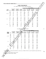
Apply  th e  indicated  c urrent  per  Table 

for  per­

manent  magnet  adjustm ent  (e. g.  C0-8,  2  times  tap 
value)  and  m easure  the  operating 

time .  

Adjust  the 

permanent  magnet  keeper  until  the  operating  time 

corresponds  to  the  value  of Table  I. 

ApplY  the  indicated  current  per  Table  I  for  the 

electromagnet  plug  adjustment  (e . g .   C0-8 ,  20  times 
tap  value )  and  measure  the  operating  time.  Adjust 

the  proper  plug  until  the  operating  time corresponds 

to  the  value  in  Table  I.  (Withdrawing  the  left  h and 
plug,  front  view ,   increases  the  operating  time  and 

withdrawing  the  right  hand  plug, front  view ,  decreases 
the  time. )  In  adjusting  the  plugs,  one  plug  should  b e  

screwed  i n   completelY  and  the  other  plug  run  i n   or 
out  until the  proper  operating  time  has  been  obtained. 

For  type 

C0- 1 1  

relay  only,  the 

1 . 3 0 

times  tap 

val ue  operating  time  from  the  number 

time  d ial  posi­

tion  is  54.9  ±5%  se conds .  It  is  important  that  the 

1 . 30 

times  tap  value  current  be  maintained  accurately .  The 
maintaining  of  th1s  current  accurately  1s  necessary 
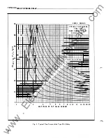
becaus e  of  the  steepness  of  the  s lope  of  the  time­
current  characteristic  (F1gu re  9. 

A  1% 

variation  in 

the 

1 . 30 

times  ta p  value  c urrent  ( including  mea surin g 

mstrument  d eviation)  will  change  the  nominal  opera­
tin g  time  by  approximately  4%. 

If 

the  operating  time 

at 

1 . 3  

times  tap  valu e   is  not  within  these  l imits ,  a 

minor  adjustment  of  the  control  s pring  will  give  the 
c orrect  operating  time  without  any  undue  effect  on 

the  minimum  p ick-up  of  the  relay .  This  check  is  to 

be  made  after  the 

times  tap  val ue  adjustment  has 

been  completed. 

Recheck  the  permanent  magnet  adjustment. 

If 

the  operating  time  for  this  calibration  point  has 
changed,  readjust  the  permanent  magnet  and  then 

recheck  the  electromagnet  plug  adjustment. 

15 

www 

. ElectricalPartManuals 

. com 

Содержание C0-11

Страница 1: ...ain pole flux The out of phase fluxes thus produced in the air gap cause a contact closing torque The electromagnets for the types C0 2 and CO Il relays have a main coil consisting of a tapped primary winding and a secondary winding Two identical coils on the outer legs of the lami nation structure are connected to the main coil secondary in a manner so that the combination of all the fluxes produ...

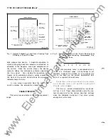
Страница 2: ...rip circuit Also during the op eration two fingers on the armature deflect a spring located on the front of the switch which allows the operation indicator target to drop A core screw accessible from the top of the switch provides the adjustable pickup range 2 OPEUTIOII IIIOICATOR AUX CURII EIIT TilUSF SECOJIDARY TEST SifiiiTCH INTERNAL SCHENAT IC DE ION COHTACTOR SWITCH AUX CURREIH TRAMSF PRht IM...

Страница 3: ...4 38 7 262 800 2 5 4 0 110 55 5 13 39 8 280 920 3 0 4 4 110 51 5 37 42 8 312 1008 2 6 3 5 4 8 110 47 5 53 42 8 329 1120 4 0 5 2 110 45 5 72 46 0 360 1216 5 0 5 6 110 41 5 90 50 3 420 1500 6 0 6 0 110 37 6 54 54 9 474 1800 4 0 7 3 230 65 4 92 39 1 268 848 5 0 8 0 230 50 5 20 42 0 305 1020 6 0 8 8 230 47 5 34 44 1 330 1128 4 12 7 0 9 6 230 46 5 35 45 8 364 1260 8 0 10 4 230 43 5 86 49 9 400 1408 10 ...

Страница 4: ...E RELAY 0 AMPERE RANGE 0 5 2 5 2 6 4 12 CONTINUOUS RATING TAP AMPERES 0 5 2 7 0 6 3 1 0 8 3 7 1 0 4 1 1 5 2 0 2 5 2 2 5 3 3 5 4 5 6 4 5 6 7 8 10 12 5 7 6 8 7 7 8 8 8 9 7 10 4 11 2 12 5 13 7 16 18 8 19 3 20 8 22 5 25 28 ONE SECOND RATING AMPERES 88 88 88 88 88 88 88 230 230 230 230 230 230 230 460 460 460 460 460 460 460 POWER FACTOR ANGLE q 68 67 66 64 61 58 56 66 63 63 62 61 59 58 64 61 60 58 55 ...

Страница 5: ... 2 21 3 21 8 22 6 23 6 24 8 27 8 31 4 AT 10 TIMES TAP VALUE CURRENT LI 0 9 132 134 142 150 170 200 228 136 142 149 157 164 180 198 146 158 172 190 207 248 292 AT 20 TIMES TAP VALUE CURRENT LI 0 91 350 365 400 440 530 675 800 360 395 430 470 500 580 660 420 480 550 620 700 850 1020 TYPE C0 11 RELAY POWER FACTOR ANGLE 36 34 30 27 22 17 16 32 30 27 24 23 20 20 29 25 22 20 18 17 16 60 HERTZ VOLT AMPER...

Страница 6: ... 8 r E fitf1 EE famm 6 4 K r f 8 3 U i i_l 4 t f 2 t 1 iN t l 1 t 1 r I_ l i i t 2 _ _ _ _ I 1 f t r t il f j I 1 kK i j i r 1 I I i I I i i I I I i I 1 I j i I I _r L t 1 08 _ h r t 06 04 0 3 02 01 t t i i I I 1 t t t 1 2 ii L l 1 c _ __c__ ___ _ _ __ _ _ I II C c L _ _ _ I 1 t i c__ f El f I r J 1 I _ i I i i I i i 1 I I i I I t I i m i i t l c cc lc _ _ _ _ j_ _r r i i i 1 Jr 1 1 1 r 1 i i 1 r ...

Страница 7: ...i l i l fr r I I 1 I I II I I I 1 I I I I I I _l _ j I I lj I t t 1 I r r r f f L 1 1 1 __ _J _L R 1 _ _ _ I I i _ I 1 1 6 l o N 5 I j 3 ti l o o 2 1 1 2 I I 2 j I I I I I i f t T I ME D I AL j t t r _ 11 ooo 10 i 9 I ro a J1 oi I J No 7 I T I r l r 1 1 3 jjl j I r 1 lo o I rr 5 6 MULTIPLES Of TAP VALU E CU RREN T Fig 4 Typical Time Curve of the Type C0 5 Relay 1 I I I I I i I I i I I I I I j I I ...

Страница 8: ...RELAY 50 60 HERTZ t l i t l rt f N t f W t f t t 1 tt rttt Tl ME 0 I AL SETT I NG f 8 5 6 7 8 9 10 MULTIPLES OF TAP VALU E CUR RENT Fig 5 Typical Time Curve of the Type C0 6 Relay 12 114 16 18 20 Curve 418246 w w w E l e c t r i c a l P a r t M a n u a l s c o m ...

Страница 9: ... 1 I I 9 I I I I T IME 1 1 1 I i 10 I 1 oo I I I L 41 103H TYPICAL TIME CURVES TYPE C0 7 OVERCURRENT RELAY 50 60 HERTZ r lt 1 I D I AL SETT I N G r r 1 o 1 o I I 1 o t r r r r 3 5 6 7 8 9 10 12 1 16 lB 20 MULT I PLES OF TAP VALUE CURRENT Fig 6 Typical Time Curve of the Type C0 7 Relay Curve 418247 9 w w w E l e c t r i c a l P a r t M a n u a l s c o m ...

Страница 10: ... 11 1X 2 _ rlol _l I N No o TYPICAL TIME CURVES TYPE C0 8 OVERCURRENT RELAY 50 60 HERTZ I I I I I TIM E DIAL SETTING J 1 1 11 10 9 ro r fooo I X 1 oo _ r _ r I 1 1 r i i oo I r I 3 5 o 7 a 9 10 12 14 16 18 20 MULTIPLES OF TAP VALUE CU RR ENT Curve 418248 Fig 1 Typical Time Curve of the Type C0 8 Relay w w w E l e c t r i c a l P a r t M a n u a l s c o m ...

Страница 11: ...RTZ f 1 1 1 I I t t t t Hf 1 jl j1t t 1 _r k f Jt _ 1 1 T l ME 0 I AL SETT I NG 1 I I 1 J 2 3 ij 5 6 7 8 MU L T I PLES OF TAP VALUE CURRENT 9 10 Fig 8 Typical Time Curve of the Type C0 9 Relay 12 1 16 18 20 Curve 418249 11 w w w E l e c t r i c a l P a r t M a n u a l s c o m ...

Страница 12: ...WESTINGHOUSE ELECTRIC CORPORATION RELAY INSTRUMENT DIVISION CORAL SPRINGS FL 33065 Printed in U S A w w w E l e c t r i c a l P a r t M a n u a l s c o m ...

Страница 13: ...notes change from superseded Issue flux The out of phase fluxes thus produced in the air gap cause a contact closing torque The electromagnets for the types C0 2 and C0 1 1 relays have a main coil consisting of a tapped primary winding and a secondary winding Two identical coils on the outer legs of the lamination structure are connected to the main coil secondary in a manner so that the combinati...

Страница 14: ...spring located on the front of the switch which allows the operation indicator target to drop A core screw accessible from the top of the switch provides the adjustable pickup range 2 INTERNAL SCHEMATIC OE JOH COHTACTOR SW I TCH OPERATION IND ICATOR AUX CURRENT TRAHSF Pill AUX Ci JIIUHT TRAHSF SECONDARY INDICATING INSTAIHAHEOUS TR IP UltiT IWUCTIOM UII IT CMASSIS OPEIIATED SHORTING SW ITCII TEST S...

Страница 15: ... 04 38 7 262 800 2 5 4 0 1 10 55 5 13 39 8 280 920 3 0 4 4 1 10 51 5 37 42 8 3 1 2 1008 2 6 3 5 4 8 1 10 47 5 53 42 8 329 1 120 4 0 5 2 1 10 45 5 72 46 0 360 1216 5 0 5 6 1 10 41 5 90 50 3 420 1500 6 0 6 0 1 10 37 6 54 54 9 474 1800 4 0 7 3 230 65 4 92 39 1 268 848 5 0 8 0 230 50 5 20 42 0 305 1020 6 0 8 8 230 47 5 34 44 1 330 1 128 4 12 7 0 9 6 230 46 5 35 45 8 364 1260 8 0 10 4 230 43 5 86 49 9 ...

Страница 16: ... M O D E R AT E L Y I NV E R S E T I ME R E L A Y VOLT AMPERES 270 288 325 360 462 548 630 308 342 381 417 448 540 624 376 450 53 1 611 699 880 1056 CONTINUOUS ONE SECOND POWER AT AT 3 TIMES AT 10 TIMES AT 20 TIMES RATING AMPERES 2 7 3 1 3 7 4 1 5 7 6 8 7 7 8 8 8 9 7 10 4 11 2 12 5 13 7 16 18 8 19 3 20 8 22 5 25 28 RATING AMPERES 88 88 88 88 88 88 88 230 230 230 230 230 230 230 460 460 460 460 460...

Страница 17: ... 228 136 142 149 157 164 180 198 146 158 172 190 207 248 292 675 800 360 395 430 470 500 580 660 420 480 550 620 700 850 1020 VOLT AMPERES CONTINUOUS ONE SECOND POWER AT AT 3 TIMES AT 10 TIMES AT 20 TIMES RATING AMPERES 1 7 1 9 2 2 3 5 3 0 3 5 3 8 7 0 7 8 8 3 9 0 10 0 1 1 0 12 0 14 16 17 18 20 22 26 RATING AMPERES 56 56 56 56 56 56 56 230 230 230 230 230 230 230 460 460 460 460 460 460 460 FACTOR ...

Страница 18: ... l O co 6 1 SEC I I I I I I 1 J 1 1 J r J 1 1 ll 1 I 1 1 j 1 I 1 f I N I I i l 1 J I 1 I 1 i 1 1 1 i I I MULT I PLES O F TAP VALUE CURRENT Fig 3 Typical Time Curves o f the Type C0 2 Relay CURVE l 182 w w w E l e c t r i c a l P a r t M a n u a l s c o m ...

Страница 19: ... I I I i I I I I i I I I I I I I I I I I II I I I I l I I I I l I I I I I I r I i I I 1 j I I i I i I 1 1 I Ll I I J I I I I 1 I I I II I l i I i I I i I I I l l I I I I I I JLI II I l I II i I I I I I i I I I I _l I l I i I I I j_ I I I I i I I I I I l l I I I I I I I I I I 1 i I I I I I l l l I I I l I I i i I I l I I I l I 1 1 I 1 1 i I I I i I I I I I I i I 1 I I I I i I I j_ l I lll ll 1 1 lJ...

Страница 20: ...I 1 1 I i I 1 1 I T I ME I TT 1 1 N 10 1 _ N 1 1 1 r J _ 9 _ 8 I 1 i 7 I 6 1 o 1 i N 5r 4 1 I X I 4 3 ITi Jt r m 2 h 1 J _ d l rtt l 1 r 112 _ l 1 Hf f I tf I f l 2 3 5 I r o I I I s o_ o I I I I I I I I I Ill I D I AL SETT I NG I 6 7 8 9 10 12 114 16 18 20 MU L T I P L E S O F TAP VALU E CURRENT Fig 5 Typical Time Curves o f the Type C0 6 Relay w w w E l e c t r i c a l P a r t M a n u a l s c o ...

Страница 21: ...i t l 1 t l r i j t N J 1 1 1 t i 4 1 1 l 5 T T H rl 1 l H 1 ij 1 __ _ ___ _ f 3 roo l 2 I I 2 1 _ 1 1 1 I I __ A J1 I _l N I 1 7 N 6 5 I ij 3 2 T I ME N 1 11 1 I I I ll _k IN N 10 1 9 ooi 8 I I n I I D I AL SETT I NG I I I t I j i r r _ __ _ r MULT I PLES O F TAP VALUE CURRENT Fig 6 Typical Time Curves of the Type C0 7 Relay 9 w w w E l e c t r i c a l P a r t M a n u a l s c o m ...

Страница 22: ...u f 7 r rr r rrn MTMTtrn rrm C U R VE I8 2 TYP I CAL T I ME CU RVES TYPE co a 2 1 I I I 3 lt 5 6 7 8 MULT I PLES OF TAP VALUE CURRENT OVER CURREN T RELAY 5 0_ 0 HERT Z 9 10 12 14 16 18 20 Fig 7 Typical Time Curves of the Type C 0 8 Relay w w w E l e c t r i c a l P a r t M a n u a l s c o m ...

Страница 23: ... 0 HERT Z I t llt H H ffi t H a t N t t tt t7 rt H i ttt t t l t 1 1 H t 1 f f lf f l l a f H t l t H l tt H Tttt ft H ct tt l t t t t t t t l 1 r 1 r m ffn H H t tt rrH r I I 1 I I H V t Y 4 r 4 1 0 1 0 I AL SETT I N G r 1 o 2 3 5 6 7 8 9 10 12 1 16 18 20 MU LT I PLES OF TAP VALU E CUR REN T Fig 8 Typical Time Curves of the Type C0 9 Relay 1 1 w w w E l e c t r i c a l P a r t M a n u a l s c o m...

Страница 24: ... o 0 03 0 02 0 01 I 2 l 5 6 7 8 9 10 1 1 1 1 1 1 l 1 l 1 1 l 1 1 I 1 1 r i I y l l 1 1 I 2 6 7 8 9 10 r r f MYLT I PLES Of TAr YALij CwiKENT 20 lO 0 _ _I r 1 f 20 30 o 1 1 10 9 7 E 5 3 2 1 2 2888655 TYP I CAL T I ME CURVES TYPE C0 1 1 OVER CURRENT RELAY 5 0 _ 0 HERT Z TIM DIAL SETT 11 Fig 9 Typical Time Curves of the Type C0 1 1 Re lay w w w E l e c t r i c a l P a r t M a n u a l s c o m ...

Страница 25: ...urvc s CAUTION Since the tap block connector screw carries oper ating current be sure that the screw is turned tight In order to avoid opening the current transformer cir cuits when changing taps under load connect the spare connector screw in the desired tap position before removing the other tap screw from the original 1 2 3 51 1 cs DEV ICE NUM ER CHART 51 DVERCURRENT RELAY TYPE CD 5 1 8 Sl PH I...

Страница 26: ...half of its normal deflection Therefore with the stationary contact resting against the backstop the index mark is offset to the right of the 0 mark by approximately 020 The placement of the various time dial positions in line with the index mark will give operating times as shown on the respective time current curves For typ e C0 1 1 rel ay only the 1 30 times tap valu e operating time from the n...

Страница 27: ...ue of the relay is most convenientlY made with the damping magnet removed With the time dial set on 0 wind up the spiral spring by means of the spring adjuster until approxi matelY 6 3 4 convolutions show Set the relay on the minimum tap setting the time dial to position 6 Adjust the control spring tension so that the moving contact will leave the backstop at tap value current l Oo c and will retu...

Страница 28: ...s sufficient current a c through the operati on md1cator to just operate it This val ue of current shoul d not be greater than 3 am peres The operation mdicator target should drop freely To change pickup adjust the core screw 1 6 6 INDICATING INSTANTANEOUS TRIP UNIT liT Tl1e making of the c ontacts and target indication shoul d occ ur at approXImately the same mstant Posi tiOn the stationary conta...

Страница 29: ... OPERATING CURRENT OPERATING RELAY DIAL MULTIPLES OF TIME MULTIPLES OF TIME TYPE POSITION TAP VALUE SECONDS TAP VALUE SECOND S C0 2 6 3 0 57 2 0 0 22 co s 6 2 37 8 0 1 0 14 30 C0 6 6 2 2 46 2 0 1 19 C0 7 6 2 4 27 2 0 1 1 1 C0 8 6 2 13 35 2 0 1 1 1 co g 6 2 8 87 2 0 0 65 C0 1 1 6 2 1 1 27 2 0 0 24 6 6 Fo r 50 hertz C0 1 1 relay 20 times op erating tim e limits are 0 24 10 5 1 7 w w w E l e c t r i ...

Страница 30: ... l 3 18 R 80 98 PAN E L LOCAT I O N S EM I FLUSH MTG PANEL CUTOUT 8 DR I LL i t G PROJ E C T I O N MTG FOR SE M I F L U S H MTG I DIA 2 HOLES 250 016 397 l 6 35 0 I 1 031 tl 031 1 031 t 1 031 1 375 R 26 19 26 19 1 26 19 26 19 I 9 5 3 I I 5 7D 7901 I L I Fig 1 2 Outline Drilling P lan lor the Circuit Opening CO Relay in the Type FT21 Case 1 8 w w w E l e c t r i c a l P a r t M a n u a l s c o m ...

Страница 31: ...w w w E l e c t r i c a l P a r t M a n u a l s c o m ...

Страница 32: ...W E S T I N G H O U S E E L E C T R I C C O R P O R A T I O N R E LAY I N STR U M E NT D IVI S I O N N EWAR K N J Printed in U S A w w w E l e c t r i c a l P a r t M a n u a l s c o m ...

Страница 33: ...e from superseded i ssue flux The out of phase fluxes thus produced in the air gap cause a contact closing torque The electromagnets for the types co 2 and C0 1 1 relays have a main coil consisting of a tapped primary winding and a secondary winding Two identical coils on the outer legs of the lamination structure are connected to the main c oil secondary in a manner so that the combination of all...

Страница 34: ... CHARACTERISTICS The relays are available in the following current range 2 AUX CUIIEIIT TRAitSF SECOIIDARY TEST SlliiTCH MOTE TERN 2 AIID 8 AlE TO IE JUMPUED AT IIU Y CAll INTERNAL SCMEMATIC DE lOll COIITACTOR SIITCII AUX CURIEIIT TRAIISF PRIM IIIDICATI IIG IIISTA IITUEOtiS TRIP UIIIT I IIDUCTIOM LUIIT Clt lJSIS OPEilAT 0 IKOITIMG SWITCH CUIIfMT TEST IACI l83A054 Fig 2 Internal Schematic of the Ci...

Страница 35: ...2 0 3 1 1 10 59 5 04 38 7 262 800 2 5 4 0 110 55 5 13 39 8 280 920 3 0 4 4 1 10 51 5 37 42 8 312 1008 2 6 3 5 4 8 1 10 47 5 53 42 8 329 1 120 4 0 5 2 110 45 5 72 46 0 360 1216 5 0 5 6 110 41 5 90 50 3 420 1500 6 0 6 0 110 37 6 54 54 9 474 1800 4 0 7 3 230 65 4 92 39 1 268 848 5 0 8 0 230 50 5 20 42 0 305 1020 6 0 8 8 230 47 5 34 44 1 330 1128 4 12 7 0 9 6 230 46 5 35 45 8 364 1260 8 0 10 4 230 43 ...

Страница 36: ...88 325 360 462 548 630 308 342 381 4 17 448 540 624 376 450 531 611 699 880 1056 C 0 7 M O D E R AT E L Y INV E R S E T I M E R E L A Y CONTINUOUS ONE SECOND POWER AT VOLT AMPERES AT 3 TIMES AT 10 TlMES AT 20 TlMES RATING AMPERES RATING AMPERES FAC IDR TAP VALUE TAP VALUE TAP VALUE TAP VALUE 2 7 3 1 3 7 4 1 5 7 6 8 7 7 8 8 8 9 7 10 4 1 1 2 1 2 5 13 7 16 18 8 19 3 20 8 22 5 25 28 88 88 88 88 88 88 ...

Страница 37: ... 64 2 75 2 38 2 46 2 54 2 62 2 73 3 00 3 46 T Y P E C0 1 1 R E LAY POWER AT FACTOR TAP VALUE ANGLE CURRENT 36 34 30 27 22 17 16 32 30 27 24 23 20 20 29 25 22 20 18 17 16 0 72 0 75 0 81 0 89 1 13 1 30 1 48 0 73 0 78 0 83 0 88 0 96 1 07 1 23 0 79 0 89 1 02 1 10 1 23 1 32 1 8 21 21 21 1 21 2 22 23 5 24 8 21 21 1 21 5 22 22 7 24 25 2 21 3 21 8 22 6 23 6 24 8 27 8 31 4 132 134 142 150 170 200 228 136 1...

Страница 38: ...ES TYPE C0 2 OVER CURRENT RELAY I 50 60 CYCL ES I I I I I I I I I I I I 1 1 I I T I ME D I AL SETT I N G 1 1 I I I 10 _l lo l g I X I 11 8 i j N 7 l ioo I 6 i o 5 I 1 o I i 4 I I I too I 3 I r 1 I 1 o i 2 r r 1 I I I I 1 2 2 3 5 6 7 8 9 10 12 11 16 18 20 MUL T I PL ES OF TAP VALUE CURRENT Fig 3 Typical Time Curves of the Type C0 2 Relay w w w E l e c t r i c a l P a r t M a n u a l s c o m ...

Страница 39: ... TYP I CAL T I ME cuRVES TYPE C0 5 ovER CU RREN T RElAY 50 60 CYC L ES I I I I II I I IT J I I I I i I I I I I II I I I I l i I I I I I i I I I i li I I I II li I I T I I m T I IT T I I I j I I I I I I I I I I T T I I I II I T IT T i r I T I I II 11 I I I 1 i I I I I i I I I I I I I I I j 1 1 I I I I I T I I T I I I I I I T I ME D I AL SETT I NG w tim I I I I I I I i II i 1 1 1 1 lo l I I I l 5 I ...

Страница 40: ...4 if 1 2 1 1 1 1QN m UH 4 J f l 4 1 f J 9 1 I f J 4 j frt f ll 1 loo l f t 8 I I l 1 4 1 r f rH 1 ff 7 1 f k l F v f f 11 1 1 f H kl H o l 5 f f 1 l 2 1 1 1 h 1 t 1 t H 2 l 3 5 6 7 8 9 10 12 1 16 18 20 MUL T I P L ES O F TAP VALU E CURRENT Fig 5 Typical Time Curves of the Type C0 6 Relay w w w E l e c t r i c a l P a r t M a n u a l s c o m ...

Страница 41: ...TYPE C0 7 I I I I O VE R CURRENT RELAY I 1 I I 1 I I I 50 60 CYCL ES I I I I I I I I I N I I I I I I i l I I I 1 T I ME D I AL SETT I N G 1 1 1 1 I I 10 1 9 e loo 7 1 o r 6 r r 5 I r l i 1 r r _ 3 t r r 2 r r _ 1 1 2 I I 2 3 5 e 1 e e 10 12 14 16 lB 20 MULT I PL ES OF TAP VALUE CU RRENT Fig 6 Typical Time Curves o f the Type C0 7 Relay 9 w w w E l e c t r i c a l P a r t M a n u a l s c o m ...

Страница 42: ... I I i I I I I I I I I I I I I I I I I I I I I I i I I I I I I 1 I I T I M E D I AL S ET T I N G I I I I II I 1 1 I I I 1 1 10 N _ I I 5 1 I I 1 1 I N 9 8 7 J 6 o I I I I _ N I I I N I I I I I N I _ roo I I I I I I I n1 1 I I I I I I I i I I X I i ll I X I f1 o No I l N I I I N I I N oo l o ll lo I t 1 l I I I _ I I 3 l 5 6 7 8 9 10 12 14 16 18 20 MULT I PLES O F TAP VALU E CURRENT Fig 7 Typical T...

Страница 43: ... T I ME CURVES TYPE C0 9 I I OVER CURRENT RELAY i I 50 60 CYCLES I I 1 I I I I i I l i I I I I I I T I ME D I AL SETT I NG I 1 1 I T 10 i 9 i 1 I 8 7 N I i 6 I 5 I I l 1 3 2 I I 1 r o 1 r r r I I I 2 3 5 6 7 8 9 10 12 14 16 18 20 MU LT I P L ES OF TAP VALUE CU RREN T Fig 8 Typical Time Curves of the Type C0 9 Relay 1 1 w w w E l e c t r i c a l P a r t M a n u a l s c o m ...

Страница 44: ...0 05 0 0 0 03 0 02 0 01 1 2 1 1 i IW l l 3 li 6 7 8 9 10 W 1 l 20 30 0 2888655 TYP I CAL T I NE CURVES TYP E C0 1 1 OVER CU RRENT RELAY eo eo CYCLrs I 1 1 1 t i 0 r 2 3 6 7 8 9 10 _ _ r I 1 to 20 30 o MULT I PLES Of TAr VALUE CUiiENT 11 10 9 7 E s 3 2 1 1 Tlt4E 0 IAL SETTINii Fig 9 Typical Time Curves of the Type CO l l Re lay w w w E l e c t r i c a l P a r t M a n u a l s c o m ...

Страница 45: ...tor screw carries oper ating current be sure that the screw is turned tight In order to avoid opening the current transformer cir cuits when changing taps under load connect the spare connector screw in the desired tap position before removing the other tap screw from the original 1 2 3 51 1 cs DEi ICE NUN8ER CHART 51 OVERCURRENT RELAY TYPE CO 51 8 51 PH 1 T P 2 PH 3 CS DE I ON CONTACTOR SWITCH I ...

Страница 46: ...half of its normal deflection Therefore with the stationary contact resting against the backstop the index mark is offset to the right of the 0 mark by approximately 0 20 The placement of the various time dial po sitions in line with the index mark will give operating times as shown on the respective time current curves For typ e C0 1 1 relay only the 1 30 times tap valu e operating time from the ...

Страница 47: ...rrent value of the relay i s most conveniently made with the damping magnet removed With the time dial set on 0 wind up the spiral spring by means of the spring adjuster until approxi mately 6 3 4 convolutions show Set the relay on the minimum tap setting the time dial to position 6 Adjust the control spring tension so that the moving contact will leave the backstop at tap value current l Oo c and...

Страница 48: ...Pass sufficient current a c through the operation mdicator to just operate it This value of current should not be greater than 3 amperes The operation indicator targe t should drop freely To change pickup adjust the core screw 16 6 INDICATING INSTANTANEOUS TRIP UNIT liT Tl1e making of the contacts and target indication should occur at approximately the same mstant Posl tlon the stationary contact ...

Страница 49: ...T OPERATING CURRENT OPERATING RELAY DIAL MULTIPLES OF TIME MULTIPLES OF TIME TYPE POSITION TAP VALUE SECONDS TAP VALUE SECONDS C0 2 6 3 0 57 2 0 0 22 co 5 6 2 37 8 0 1 0 14 30 C0 6 6 2 2 46 2 0 1 19 C0 7 6 2 4 27 20 1 1 1 CO B 6 2 13 35 20 1 11 C0 9 6 2 8 87 2 0 0 65 C0 1 1 6 2 11 27 2 0 0 24 j L For 50 cycle C0 1 1 rel ay 20 times operating time limits are 0 24 10 5 1 7 w w w E l e c t r i c a l ...

Страница 50: ... ELS 19 SC RE W 16 F O IC 1 NEL USE 16 18 IUD o qo 3 2 SCREW 41 DI A IERM N 6 L AN D MOUNT I N G Dt to 1 NOTE Al L CIMEWS 0 IW I C f I f I PANE CUTOUT t DRILL Gr r OR SEt 41 F U ATG Fig 12 Outline Drilling Plan for the Circuit Opening CO Relay in the Type FT21 Case 57 D 7901 w w w E l e c t r i c a l P a r t M a n u a l s c o m ...

Страница 51: ...w w w E l e c t r i c a l P a r t M a n u a l s c o m ...

Страница 52: ...W E S T I N G H O U S E E L E C T R I C C O R P O R A T I O N R E LAY I N STR U M E NT D IVI S I O N N EWAR K N J Printed in U S A w w w E l e c t r i c a l P a r t M a n u a l s c o m ...

Отзывы: