


T Y P E CO CIRCUIT O P EN I NG R E LAY
s tationary contact s houl d have a mimmum of 1/3 2"
wip e . The bridgin g moving contact should touch both
stationary contacts simultaneously.
ROUTINE MAINTENANCE
All relays should be inspected periodically and
the time of operation should be checked at least
once every year or at such other time intervals as
may be dictated by experience to be suitable to the
particular application. Phantom loads should not be
used in testing induction-type relays because of the
resulting distorted current wave form which produces
an error in timing.
All contacts should be periodically cleaned . A
contact
burnisher
tt
1 82A836H0 1 is recommended
for this purpose . The use of abrasive material for
cleaning contacts is not recommended, because of
the danger of embedding s mall particles in the face
of the soft silver and thus impairing the contact.
CAL I B RAT ION
Use of the following procedure for calibrating the
relay if the relay has been taken apart for repairs or
the adjustments disturbed.
This procedure should
not be used until it is apparent that the relay is n ot
in proper working order. (See "Acceptance Check " )
C O UNIT
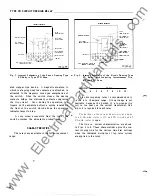
1 . CONTACTS
a) By turning the time dial , move the moving con
tacts until they defl ect th e stationary contact
to a position wh ere the s tationary c ontact is
resting against its backstop. The index mark
l ocated on th e movement frame should coincide
with the "0" mark on the time dial.
b) For relay& identified with a "T " , l ocated at
l ower l eft of stationary c ontact bl ock , the index
mark on the movement frame will coincide with
the "0" mark on the time dial when the s tation
ary contact has moved through approximately
one-hal f of its normal defl ection. Therefor e ,
with th e stationary contact resting against the
backstop, the index mark is offset
to
the right of
the "0" mark by approxima tely . 020". The
placement of the various time dial positions in
line with the index mark will give operatin g
times as shown on the res pective time-current
curves .
2. MINIMUM TRIP CURRENT
The adjustment of the spring tension in setting
I . L . 41 ·103 E
the minimum trip current value of the relay i s most
conveniently made with the damping magnet removed.
With the time dial set on "0" , wind up the spiral
spring by means of the spring adjuster until approxi
m ately 6-3/4 convolutions show.
Set the relay on the minimum tap setting, the
time dial to position 6.
Adjust the control spring tension so that the
moving contact will leave the backstop at tap value
current
+ l .Oo/c
and will return to the backstop at tap
value current - 1 . 0%.
3 . TIME C URVE CALIBRATION
Install the permanent magnet.
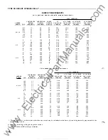
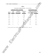
Apply the indicated current per Table I for per
manent magnet adjustm ent (e . g. C0-8, 2 times tap
value) and m easure the operating time. Adjust the
permanent magnet keeper until the operatin g time
corresponds to the v alue of Table I .
Apply the indicated current per Table I for the
electromagnet plug adjustment (e .g. C0-8 , 20 times
tap value) and measure the operating tim e . Adjust
the proper plug until the operating time c orresponds
to the value in Table I . (Withdrawing the left hand
plug, front view , increases the operating time and
withdrawing the right hand plug, front view, decreases
the time. ) In adjusting the plugs , one plug should b e
screwed i n completely and the other plug run in or
out until the proper operating time has been obtained.
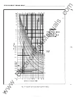
For type C0- 1 1 relay only, the 1 . 3 0 times tap
val ue o perating time from the number 6 time dial posi
tion is 54.9 ±5% se cond s . It is important that the 1 . 30
times tap value current be maintained accurately. The
maintaining of this c urrent accurately is necessary
becaus e of the stee pne ss of the s lope of the time
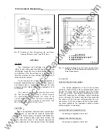
current characteristic (Fi gure 9 . A 1% variation in
the 1 . 30 times tap value current ( including measurin g
instrument deviation) will change the nominal opera
ting time by a pproximately 4%. If the operating time
at 1. 3 times tap val ue is not within these l imits , a
minor adjustment of the control spring wi ll gi ve the
c orrect operating time without any undue effect on
the minimum p ick-up of the relay. This check is to
be made after the 2 times tap val ue adjustment has
been compl eted.
Recheck the permanent magnet adjustment.
If
the operating time for this calibration point has
changed , readjust the permanent magnet and then
recheck the electromagnet plug adjustment.
15
www
. ElectricalPartManuals
. com