T Y P E CO CIRCUIT O P E N I NG RE LAY
INDICATING INSTANTANEOUS TRIP
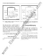
The core screw must be adjusted to the va lue of
Pick-up c urrent desired.
The nameplate data will furnish the actual cur
rent range that may be obtained from the liT unit .
I NSTAL LATION
The relays should be mounted on switchboard
panels or their equivalent in a location free from dirt ,
moisture , excessive vibration and heat.
Mount the
relay vertically by means of the mo unting stud for the
type F'T projection CA.se or by means of the four
mounting holes on the flange for the semi-flush type
FT cas e. Either the stud or the mounting screws may
be utilized for grounding the relay. The electrical
connections may be made directly to the terminals by
means of scre ws for steel panel mounting or to the
terminal stud furnished with the relay for thick p anel
mounting. The terminal stud may be easily removed
or inserted by locking two nuts on the stud and then
turning the proper nut with a wrench.
For detail information on the FT c ase refer to
IL 4 1-076.
ADJUSTM E NTS AND MAI N T E NANCE
The proper adjustme nts to insure correct opera
tion of this relay have been made at the factory. Upon
rece ipt of the relay no c ustomer adjustme nts , other
than those covered under "SETTINGS" should be
required.
ACC EPTANCE CHECK
The following check is recommended to insure
that the relay is in proper working order:
1. CONTACTS
a) By turning the time dial , move the moving con
tacts until they defl ect the stationary contact
to a position where the st ationary contact is
resting against its backstop . The index mark
located on the movement frame shoul d coincide
with the
"0"
mark on t he time dial.
b) For relays ide ntified with a "T" , l ocated at
lower l eft of statio nary contact b lock , the index
mark on the movement frame wi ll coincide with
the
' ' 0 ' '
mark on the time dial when the station
ary contact has moved through approximately
1 4
one-half of its normal defl ection. Therefore ,
with the stationary contact resting against t he
backstop , the index mark is offs et to the r ight of
the
" 0 "
mark by a pproximately . 0 20 ". The
p l acement of the various time dial positions in
line with the index mark will give op erating
times as shown on the respective time-cur rent
curves.
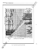
For typ e C0- 1 1 rel ay only, the 1 . 30 times tap
valu e operating time from the number 6 time di al
position is 54 . 9
±
5% seconds and should be check
ed first. It is impo rtant that the 1 . 30 times tap value
current be maintained accurately. The maintaining
of thi s current accurately is necessary because of
the steepness of the slop e of the time-current char
acteri sti c (Fi gure 9 ) . A 1% variation in the 1 . 30
times tap value current ( including measuring instru
ment deviation) will change the nominal operating
time by approximately 4%.
2. MINIMUM TRIP CURRENT
Set the time dial to position 6. Alternately apply
tap value current plus 3% and tap value current minus
3%. The moving contact s hould leave the backstop
at tap value c urrent plus 3% and should return to the
backstop at tap value current minus 3%.
3. TIME CURVE
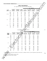
Table I s hows the time curve calibration points
for the various type s of relays. With the time dial set
to the indicated position , apply the currents speci
fied by Table I, ( e . g. for the CQ- 2 , 3 and 20 time s
tap value current) and measure the operating time of
the relay. The operating times s hould equal those of
Table I plus or minus 5 percent.
4. DE-ION CONTACTOR SWITCH
The de-ion contactor switch should operate with
a minimum of 4 amperes a-c applied.
5. OPERATION INDICATOR
The operation indicator should operate with a
minimum of 3 amperes a-c applied.
The operation
indicator target should drop freely.
6. INDICATING INSTANTANEOUS TRIP UNIT (liT)
The core screw which is adj ustable from the top
of the trip unit determine s the pickup value . The trip
unit has a nominal ratio of adjustment of
1
to 4 and
an accuracy within the limits of 1 0% .
The making of the contacts and target indication
shou l d occur at approx imately the same instant. The
www
. ElectricalPartManuals
. com


