background image

Lit. No. 79551, Rev. 07 

19 

June 15, 2022

GETTING TO KNOW YOUR SNOWPLOW

There is no need to unhook the chains or 

the hydraulic hoses. When the lift frame is 

pinned to the stands and locked in place (see 

blade label or the Removing Snowplow from 

Vehicle & Storage section of this manual), the 

complete UltraMount

®

 2 snowplow can be easily 

moved around on most hard surfaces.

BLADES

WESTERN

®

 snowplows with steel blades are 

constructed of heavy‑gauge steel. To increase 

rigidity and strength, the blades are reinforced with 

several vertical ribs. The top edges are formed for 

added strength and improved appearance.

WESTERN snowplows with poly blades are 

constructed of a high molecular weight polyethylene 

sheet that is supported with structural steel.

WESTERN blades have replaceable high‑carbon 

steel cutting edges bolted to the bottom. 

Straight blade, PRODIGY™, WIDE‑OUT™, and 

WIDE‑OUT™ XL cutting edges should be replaced 

when worn to the bottom edge of the blade. 

MVP PLUS™ and MVP 3™ cutting edges should 

be replaced when worn to within 1" (2.5 cm) of the 

carriage bolts. (See the Maintenance section in this 

manual.)

Your new blade's steel components are protected 

with a baked‑on ULTRAFINISH™ powder coat 

over a base primer coat that resists cracking, 

corrosion, scratching, and rust. This coating—

many times thicker than paint—will maintain its 

luster and glossy good looks. It can be touched up 

when necessary.

Blade guides are included with your complete 

snowplow. These help the operator to visualize the 

edges of the blade and aid in blade positioning.

Содержание UltreMount 2

Страница 1: ...CAUTION Read this manual before operating or servicing snowplow This document supersedes all editions with an earlier date SNOWPLOW OWNER S MANUAL Original Instructions June 15 2022 Lit No 79551 Rev 07 ...

Страница 2: ...ler Address ________________________________________________________________________ Vehicle Model Year ____________________________________________________________________ Snowplow Model Year __________________________________________________________________ Snowplow Type Size ____________________________________________ Weight ____________ lb kg Ballast No____ Yes____ Amount_____________lb kg Fl...

Страница 3: ......
Страница 4: ...cessories and Options 26 Mounting Snowplow to Vehicle 28 Operating Your Snowplow 30 PRODIGY Straight Blade Hand Held Control 30 PRODIGY Straight Blade Joystick Control 33 MVP PLUS MVP 3 WIDE OUT WIDE OUT XL Hand Held Control 37 MVP PLUS MVP 3 WIDE OUT WIDE OUT XL Joystick Control 41 FLEET FLEX Electrical System 46 SECURITY GUARD System 47 Smooth Stop 51 One Touch FLOAT 52 MVP PLUS Blade Positions ...

Страница 5: ...ges 85 PRODIGY Wing Cutting Edges 87 Aiming Headlamp Beams 88 Straight Blade Hydraulic Unit Cover 90 Hydraulic System Maintenance 92 Fluid Level 92 Annual Fluid Change 94 House Routing Diagrams 96 Air Removal HTS PRODIGY Straight Blades 98 Air Removal MVP PLUS MVP 3 99 Air Removal WIDE OUT WIDE OUT XL 100 Hose or Fitting Replacement 101 Installing Hydraulic Fittings and Hoses 102 Fuse Replacement ...

Страница 6: ...best Contact your snowplow outlet for maintenance service or any other assistance you may require Your WESTERN snowplow FloStat hydraulic unit has a serial number Record this serial number on the Snowplow Owner Data Sheet at the front of this manual Before using your WESTERN snowplow make sure that your vehicle is equipped with all the vehicle manufacturer s and our required options for plowing Mo...

Страница 7: ...al equipment reliability and efficiency is to purchase only genuine Factory Original parts and accessories Will fit parts and accessories can alter your snowplow s performance characteristics and may affect your product warranty Protect your investment by staying with the best original WESTERN parts and accessories from your local WESTERN outlet ...

Страница 8: ...utlet SAFETY DEFINITIONS NOTE Indicates a situation or action that can lead to damage to your snowplow and vehicle or other property Other useful information can also be described WARNING Indicates a potentially hazardous situation that if not avoided could result in death or serious personal injury CAUTION Indicates a potentially hazardous situation that if not avoided may result in minor or mode...

Страница 9: ...2 STEP 3 STEP 2 STEP 1 Handle Stand Hook Pull Lock Pin Receiver Pin 69661 05 Pull and hold Lock Pin out then rotate Handle DOWN and release Lock Pin It must lock into LOWER hole Push top of Shoe DOWN Shoe will be on the ground MOUNTING PLOW ON REMOVING PLOW OFF U S patents 6 145 222 6 209 231 6 526 677 6 711 837 6 928 757 6 941 685 7 400 058 7 430 821 7 737 576 CAN patents 2 354 257 2 639 052 and ...

Страница 10: ...22 SAFETY Code Definition YY 2 Digit Year MM 2 Digit Month DD 2 Digit Day LL 2 Digit Location Code XXXX 4 Digit Sequential Number ZZZZZZ 5 to 7 Digit Blade Assembly PN YYMMDDLLXXXXZZZZZ ZZZZZ zzzzz YYMMDDLLXXXXZZZZZ Serial Number Label ...

Страница 11: ...ctedly or damaging hydraulic components Failure to do this could result in serious personal injury WARNING Remove blade assembly before placing vehicle on hoist CAUTION Read Owner s Manual before operating or servicing snowplow CAUTION Plowing speed should not exceed 10 mph 16 km h CAUTION See your WESTERN outlet for application recommendations CAUTION Transport speed should not exceed 45 mph 72 k...

Страница 12: ...placement including fuse ratings and locations is located in the Maintenance section of this Owner s Manual PERSONAL SAFETY Remove the ignition key and put the vehicle in PARK or in gear to prevent others from starting the vehicle during installation or service Wear only snug fitting clothing while working on your vehicle or snowplow Do not wear jewelry or a necktie and secure long hair Wear safet...

Страница 13: ...ay attention to the road Wait until it is safe to operate mobile communication equipment such as cell phones text messaging devices pagers or two way radios VENTILATION WARNING Gasoline is highly flammable and gasoline vapor is explosive Never smoke while working on vehicle Keep all open flames away from gasoline tank and lines Wipe up any spilled gasoline immediately WARNING Vehicle exhaust conta...

Страница 14: ...to the whole body CAUTION Batteries normally produce explosive gases which can cause personal injury Therefore do not allow flames sparks or lit tobacco to come near the battery When charging or working near a battery always cover your face and protect your eyes and also provide ventilation Batteries contain sulfuric acid which burns skin eyes and clothing Disconnect the battery before removing or...

Страница 15: ...s before installation The Quick Match selection system has specific vehicle and snowplow requirements WESTERN Quick Match selection system is based on available vehicle capacity for snowplow equipment on a representative vehicle equipped with options commonly used for plowing and with 300 lb 136 kg of front seat occupant weight Weights of front seat occupants can be adjusted above 300 lb 136 kg bu...

Страница 16: ...it be secured properly behind the rear axle A ballast retainer kit PN 62849 is available from your WESTERN outlet NOTE The ballast retainer kit is for snowplow vehicles requiring ballast See your WESTERN outlet for the correct amount of ballast required Include the weight of the retainer as part of the ballast requirement Sand bags are recommended for use as ballast NOTE Ballast recommended and it...

Страница 17: ...e lower lift frame and stand leg The holes will accept 1 3 cm trailer hitch pin locks which are available at most auto supply or trailer equipment stores These holes used with locks may be used to secure the snowplow assembly on or off the truck to deter theft The snowplow shall be installed according to instructions supplied WESTERN outlets are trained to provide this service and other services f...

Страница 18: ...lecular weight polyethylene sheet that is supported with structural steel WESTERN blades have replaceable high carbon steel cutting edges bolted to the bottom Straight blade PRODIGY WIDE OUT and WIDE OUT XL cutting edges should be replaced when worn to the bottom edge of the blade MVP PLUS and MVP 3 cutting edges should be replaced when worn to within 1 2 5 cm of the carriage bolts See the Mainten...

Страница 19: ...ent in the Maintenance section of this manual The quadrant is attached to the triangular A frame with a pivot bolt The pivot bolt allows the quadrant and blade to swing right or left The hydraulic unit is mounted on the front of the lift frame The hoses remain connected to the hydraulic unit and the rams The snowplow headlamps are also attached to the lift frame MVP PLUS MVP 3 Blades The wings are...

Страница 20: ...plicing The headlamps conform to Federal Motor Vehicle Safety Standards FMVSS WARNING Your vehicle must be equipped with snowplow headlamps and directional lights When the electrical plugs are connected the vehicle headlamps will automatically switch to the snowplow headlamps when they are turned ON When the electrical plugs are disconnected the headlamps will automatically switch to vehicle headl...

Страница 21: ... mount is fastened to the underside of the vehicle frame and provides the primary connecting point between the snowplow and the vehicle Two removable receiver brackets are attached to the mount using pins and hairpin cotters The receiver brackets are easily removed to provide more road clearance during the non plowing months of the year Driver side receiver shown Receiver Bracket Vehicle Mount Hai...

Страница 22: ...ehicle is turned to ACC or ON The ON OFF button on the cab control allows you to turn OFF the control and prevent hoist movement even when the ignition switch is ON The control ON OFF button serves as an emergency stop if required Turn the vehicle ignition switch to the ON or ACCESSORY position The control backlight will illuminate Press the ON OFF button on the control The power indicator light g...

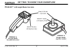
Страница 23: ... 2022 GETTING TO KNOW YOUR SNOWPLOW PRODIGY Straight Blade Controls Power Indicator Light red ON OFF Switch emergency stop ON OFF Button emergency stop PRODIGY Straight Blade Hand Held Control PRODIGY Straight Blade Joystick Control ...

Страница 24: ...OUR SNOWPLOW MVP PLUS MVP 3 WIDE OUT WIDE OUT XL Blade Controls Power Indicator Light red ON OFF Switch emergency stop ON OFF Button emergency stop MVP PLUS MVP 3 WIDE OUT WIDE OUT XL Joystick Control MVP PLUS MVP 3 WIDE OUT WIDE OUT XL Hand Held Control ...

Страница 25: ...s all types of snow quickly and cleanly CARBIDE STEEL CUTTING EDGE Carbide steel edges provide superior durability and performance with longer wear compared to a traditional steel cutting edge Unmatched wear resistant properties ensure long life and exceptional performance CURB GUARD KIT Designed to fit on the ends of the cutting edges these guards protect against scraping the bottom edge of the b...

Страница 26: ...ern Products recommends that snowplow owners apply dielectric grease to all electrical connections on a regular basis HIGH WEAR SHOES High wear shoes offer maximum protection against blade and or base channel wear on rocky and or abrasive surfaces hard pack gravel For a complete listing of available options and accessories for your snowplow model please visit www westernplows com ...

Страница 27: ...s fully seat inside the receiver brackets Turn the vehicle ignition to the OFF position WARNING Keep 8 2 4 m clear of the blade when it is being raised lowered or angled Do not stand between vehicle and blade or directly in front of the blade If the blade hits or drops on you you could be seriously injured WARNING Inspect snowplow components and fasteners for wear or damage whenever attaching or d...

Страница 28: ...will lift off the ground 2 Pull and hold the lock pin out then rotate the handle UP and release the lock pin It must lock into the UPPER hole The stand hook must grip the receiver pin 3 Repeat Steps 1 and 2 on other side of snowplow Not required for HTS blades 4 Connect the electrical plugs ON Handle Shoe Handle Receiver Pin Stand Hook Pull Lock Pin ON ...

Страница 29: ...ergency stop if required Function Time Outs To limit the amount of electrical energy required from the vehicle all control functions except LOWER FLOAT time out stop automatically after a period of time The blade will coast to a stop The time outs are written into the programming and vary by snowplow model NOTE If a control function times out before the desired blade movement is complete release t...

Страница 30: ...escription of Operation RAISE Press this button to raise the blade and cancel the FLOAT mode LOWER Press this button to lower the blade Release the button to stop the blade at desired height FLOAT Press the LOWER button and hold second to activate this mode The FLOAT light in the upper left corner of the control face will illuminate The blade will lower to the ground surface and follow the contour...

Страница 31: ...blade right NOTE If a control function times out before the desired blade movement is complete release the button and press it again SECURITY GUARD System 1 2 3 4 The four round buttons located to the left and right of the LOWER and RAISE buttons will operate the SECURITY GUARD system See SECURITY GUARD System in this section for more information OPERATING YOUR SNOWPLOW ...

Страница 32: ...he vehicle ignition switch are both ON and the electrical connections to the snowplow are completed The ON OFF switch operates as an emergency stop if required WARNING To prevent accidental movement of the blade always move the ON OFF switch to OFF whenever the snowplow is not in use The power indicator light will turn OFF NOTE If a control function times out before the desired blade movement is c...

Страница 33: ...being idle for 20 minutes To reactivate the control after a shutdown move the ON OFF switch to OFF then back to ON Optional Control Features The control ships from the factory with the Smooth Stop feature enabled and the one touch FLOAT feature disabled To change these default settings see Smooth Stop and One Touch FLOAT later in this section of the Owner s Manual Control Lever Movement From the c...

Страница 34: ...e the control lever to the LOWER position and hold second to activate this mode The FLOAT light in the upper right corner of the control face will illuminate The blade will lower to the ground surface and follow the contour of the surface as it dips or rises Function does not time out however the control will shut down after 20 minutes of nonuse Move the lever to the RAISE position momentarily to ...

Страница 35: ...le the blade right NOTE If a control function times out before the desired blade movement is complete release the lever to the center position then move it back into the desired function SECURITY GUARD System 1 2 3 4 Moving the control lever diagonally from the center position toward any of the four digits on the face of the control body will operate the SECURITY GUARD system See SECURITY GUARD Sy...

Страница 36: ...top if required Function Time Outs To limit the amount of electrical energy required from the vehicle all control functions except LOWER FLOAT time out stop automatically after a period of time The blade will coast to a stop The time outs are written into the programming and vary by snowplow model NOTE If a control function times out before the desired blade movement is complete release the button...

Страница 37: ...ovements described in the table Function Description of Operation RAISE Press this button to raise the blade and cancel the FLOAT mode LOWER Press this button to lower the blade Release the button to stop blade at the desired height FLOAT Press the LOWER button and hold second to activate this mode The FLOAT light in the upper left corner of the control face will illuminate The blade will lower to...

Страница 38: ...cts while the left wing extends MVP PLUS MVP 3 NOTE If a control function times out before the desired blade movement is complete release the button and press it again Scoop Retract Blade Position The two round buttons located to the left and right of the RAISE button move both wings at the same time into the blade positions described in the following table Function Description of Operation SCOOP ...

Страница 39: ...for more information Function Description of Operation L WING Press this button on the left side of the control to move the left wing The first time the button is pressed after the control is turned ON or another function is used the wing will extend Repeated use of the same button without using another function results in movement in the opposite direction from the previous movement R WING Press ...

Страница 40: ...e vehicle ignition switch are both ON and the electrical connections to the snowplow are completed The ON OFF switch operates as an emergency stop if required WARNING To prevent accidental movement of the blade always move the ON OFF switch to OFF whenever the snowplow is not in use The power indicator light will turn OFF NOTE If a control function times out before the desired blade movement is co...

Страница 41: ...being idle for 20 minutes To reactivate the control after a shutdown move the ON OFF switch to OFF then back to ON Optional Control Features The control ships from the factory with the Smooth Stop feature enabled and the one touch FLOAT feature disabled To change these default settings see Smooth Stop and One Touch FLOAT later in this section of the Owner s Manual Control Lever Movement From the c...

Страница 42: ...e at desired height FLOAT Move the control lever to the LOWER position and hold second to activate this mode The FLOAT light in the upper right corner of the control face will illuminate The blade will lower to the ground surface and follow the contour of the surface as it dips or rises This function does not time out but the control will shut down after 20 minutes of nonuse Move the lever to the ...

Страница 43: ...the angle right position The right wing retracts while the left wing extends MVP PLUS MVP 3 Scoop Retract Blade Position Moving the control lever from the center position toward the word SCOOP or RETRACT on the face of the control body will cause both wings to move at the same time into the following blade positions Function Description of Operation SCOOP Move the control lever toward the word SCO...

Страница 44: ...URITY GUARD System in this section for more information Function Description of Operation L WING Move the control lever toward the left side of LOWER on the control face to move the left wing The first time the lever is moved into the slot after the control is turned ON or another function is used the wing will extend Repeated use of the lever in the same slot without using another function result...

Страница 45: ...r controlled programmable features These include SECURITY GUARD electrical anti theft system Smooth stop One touch FLOAT This section provides more information about each feature as well as instructions on how to enable or disable them These features are offered to give you the ability to secure your snowplow and customize your plowing experience ...

Страница 46: ...rn the vehicle ignition switch to the ON or ACCESSORY position It is not necessary to start the vehicle 2 Verify that the control power indicator is OFF If the power indicator light is red the control is ON Move the ON OFF switch to OFF or push the ON OFF button to turn the control OFF 3 To activate the SECURITY GUARD mode move the control lever to the 1 position or press the 1 button four consecu...

Страница 47: ...urity code Once you have entered your 4 digit security code the FLOAT light will stop flashing and the power indicator light will turn OFF This indicates that your 4 digit security code is entered and stored in the SECURITY GUARD system NOTE If the control is turned ON prior to completing the programming procedure your 4 digit security code will be cancelled 4 Once a 4 digit security code is estab...

Страница 48: ... If the snowplow is locked the control power indicator light will be flashing rapidly unlock the snowplow by following the Manual Unlock procedure described above 3 Move the ON OFF switch to the OFF position or push the ON OFF button to switch the control OFF Verify that the power indicator light is OFF 4 With the control OFF move the control lever to the 2 position or press the 2 button four cons...

Страница 49: ...o enter the security code before the snowplow can be activated Once the security code is established the SECURITY GUARD system recognizes that a control with the same security code is attached and does not require a manual unlock to activate the snowplow The system will recognize the control as safe and will automatically unlock The SECURITY GUARD system is only fully functional with joystick cont...

Страница 50: ...g steps Performing the sequence multiple times will toggle the feature between enabled and disabled Enable Disable Procedure 1 Turn the vehicle ignition switch to the ON or ACCESSORY position It is not necessary to start the vehicle 2 Verify that the control power indicator is OFF If the power indicator light is red the control is ON Move the ON OFF switch to OFF or push the ON OFF button to turn ...

Страница 51: ...le the feature between enabled and disabled Enable Disable Procedure 1 Turn the vehicle ignition switch to the ON or ACCESSORY position It is not necessary to start the vehicle 2 Verify that the control power indicator is OFF If the power indicator light is red the control is ON Move the ON OFF switch to OFF or push the ON OFF button to turn the control OFF 3 Move and hold the control lever to the...

Страница 52: ...ance during transport place the blade halfway between the straight and retracted vee positions The scoop position is NOT RECOMMENDED during transport The MVP PLUS snowplow can be used in five basic plowing positions Straight Blade Move both wings to form a straight blade for wide path plowing or stacking snow ...

Страница 53: ...PLOW Angled Blade Move one wing OUT and the other wing IN to form an angled blade in either direction for general plowing and widening Retracted Vee Blade Move both wings IN toward the vehicle for initial break through plowing and plowing paths or walkways ...

Страница 54: ...ING YOUR SNOWPLOW Scoop Blade Move both wings OUT away from the vehicle to form a scoop to carry snow with minimum spilloff Dogleg Blade Move one wing to straight blade position and the other OUT to scoop blade position for clean up of windrows ...

Страница 55: ...ace the blade halfway between the straight and retracted vee positions The scoop position is NOT RECOMMENDED during transport The MVP 3 snowplow can be used in five basic plowing positions Straight Blade Move both wings to form a straight blade for wide path plowing or stacking snow OPERATING YOUR SNOWPLOW ...

Страница 56: ... Move one wing OUT and the other wing IN to form an angled blade in either direction for general plowing and widening Retracted Vee Blade Move both wings IN toward the vehicle for initial plowing and plowing paths or walkways OPERATING YOUR SNOWPLOW ...

Страница 57: ...Blade Move both wings OUT away from the vehicle to form a scoop to carry snow with minimum spilloff Dogleg Blade Move one wing to straight blade position and the other OUT to scoop blade position for clean up of windrows OPERATING YOUR SNOWPLOW ...

Страница 58: ...ITIONS The PRODIGY snowplow can be used in three basic plowing positions Scoop Blade When blade is moved to straight across orientation both wings automatically angle into scoop position Angled Blade The wings automatically adjust in and out as the blade is angled left or right ...

Страница 59: ...n 3 Secure the pin with a hairpin cotter 4 Repeat Steps 1 3 on the opposite side OPERATING YOUR SNOWPLOW Straight Blade Option The wings may be pinned in position to operate as a straight blade using the hardware provided 1 Fully angle the blade to one side Lower the blade and turn the plow control and vehicle ignition OFF x 9 Clevis Pin Hairpin Cotter ...

Страница 60: ...SITIONS The WIDE OUT and WIDE OUT XL snowplows can be used in four basic plowing positions NOTE Always transport the WIDE OUT and WIDE OUT XL snowplows with both wings fully retracted OPERATING YOUR SNOWPLOW Retracted Blade Move both wings IN to form a straight blade ...

Страница 61: ...TING YOUR SNOWPLOW Scoop Blade Move both wings OUT and ahead of the vehicle to form a scoop to carry snow with minimum spilloff Dogleg Blade Move one wing to extended position and the other OUT to scoop blade position for clean up of windrows ...

Страница 62: ...Lit No 79551 Rev 07 63 June 15 2022 Extended Blade Move both wings OUT straight for an extra wide blade for clearing large areas OPERATING YOUR SNOWPLOW ...

Страница 63: ...and disconnecting the electrical plugs should switch between the vehicle and snowplow headlamps as follows Electrical plugs DISCONNECTED Vehicle headlamps function normally Electrical plugs CONNECTED Vehicle headlamp functions transfer to the snowplow headlamps On some DRL systems both the vehicle and snowplow headlamps will function Aiming the Headlamps Aim the snowplow headlamps with the snowplo...

Страница 64: ...ersonal injury Adjustment Procedure 1 Raise the blade one foot off the road surface turn the control OFF and from in front of the blade place jack stands under the cutting edge 2 Turn the control ON and lower the blade onto the jack stands Turn the control and vehicle ignition OFF 3 Remove the linchpin and slide the shoe down and out of the shoe hole straight blades and MVP 3 or shoe holder MVP PL...

Страница 65: ...remove the jack stands 8 Stand 8 feet clear of the blade when checking the height adjustment of the cutting edge to the road surface Optional MVP PLUS PRODIGY WIDE OUT WIDE OUT XL Disc Shoe Kit Actual configuration varies by model Washers Spacer Disc Shoe Shoe Holder Linchpin Straight Blade Actual configuration varies by model Washers Spacer Disc Shoe Shoe Hole Linchpin Optional MVP 3 Shoe Kit Was...

Страница 66: ...Lit No 79551 Rev 07 67 June 15 2022 OPERATING YOUR SNOWPLOW Optional PRO PLUS HD Shoe Kit Actual configuration varies by model Washers Spacer Disc Shoe Shoe Holder Linchpin ...

Страница 67: ... under Hydraulic System in the Maintenance section of this manual Relief Valves The FloStat hydraulic unit s valve manifold includes relief valves to prevent damage to the blade or vehicle if an obstacle is hit at either end of the blade When force against the blade causes the pressure in an extended ram to exceed set limits the relief valve opens allowing fluid to escape and the ram retracts The ...

Страница 68: ...ver retainer and remove the side cover See illustrations on following page 3 The quill in the valve manifold adjusts the blade drop speed Turn the quill IN clockwise to decrease drop speed Turn the quill OUT counterclockwise to increase drop speed 4 Stand 8 feet clear of the blade when checking adjustment 5 Refer to Step 2 to reinstall the cover Quill HTS Quill Straight Blades ...

Страница 69: ...Lit No 79551 Rev 07 70 June 15 2022 OPERATING YOUR SNOWPLOW Quill Quill Quill Top Cover Retainer Top Cover Retainer Bottom Cover Retainer Bottom Cover Retainer MVP PLUS MVP3 WIDE OUT WIDE OUT XL PRODIGY ...

Страница 70: ...de to the straight position 4 Turn the control OFF to lock the blade in place NOTE Overheating is unlikely under normal driving conditions but occasionally the snowplow may be positioned where it deflects air away from the radiator If this occurs stop the vehicle and raise lower or angle the snowplow slightly to correct overheating NOTE Only the driver should be in the vehicle cab when the snowplo...

Страница 71: ...or even fatal collision if you drive after drinking Please do not drink and then drive or plow Wet and hard packed snow or ice offers the worst tire traction It is very easy to lose control You will have difficulty accelerating If you do get moving you may have poor steering and difficult braking which can cause you to slide out of control Here are some tips for driving in these conditions Drive d...

Страница 72: ...ers of clothing As you get warm you can take off layers CAUTION Wear a seat belt when plowing snow Hidden obstructions could cause the vehicle to stop suddenly resulting in personal injury CAUTION Flag any obstructions that are hard to locate under snow to prevent damage to product or property WARNING Never plow snow with head out the vehicle window Sudden stops or protruding objects could cause p...

Страница 73: ...hat you know of any obstructions hidden beneath the snow such as bumper stops in parking lots curbs sidewalk edges shrubs fences or pipes sticking up from the ground If you are unfamiliar with the area to be plowed have someone familiar with the area point out obstacles 2 If possible and you have good visibility plow during the storm rather than letting snow accumulate 3 Do not exceed 10 mph 16 km...

Страница 74: ...e fully retracted vee position and make an initial pass 2 Bite into the edges using only partial blade width until the job is cut down to size for full blade plowing Rule of thumb 6 15 cm of snow plow with entire blade width 9 23 cm of snow plow with blade width 12 30 cm of snow plow with of the blade For WIDE OUT and WIDE OUT XL blades in scoop position plow all depths with entire blade width Exp...

Страница 75: ...the remaining snow from the driveway Check municipal ordinances for proper disposal of snow Clearing Parking Lots 1 Clear areas in front of buildings first With the blade raised drive up to the building Drop the blade and back drag the snow away from the building When the snow is clear of the buildings turn the vehicle around and push the snow away from the buildings toward the outer edges of the ...

Страница 76: ...RNING Lower the blade when the vehicle is parked Keep 8 2 4 m clear of the blade Temperature changes could change hydraulic pressure causing the blade to drop unexpectedly or damaging hydraulic components Failure to do this could result in serious personal injury CAUTION Do not use any snowplow or mount components as an attachment point when retrieving towing or winching a disabled or stuck vehicl...

Страница 77: ...w to drop unexpectedly REMOVING SNOWPLOW OFF CAUTION Store PRO PLUS PRO PLUS HD PRO PLOW Series 2 MIDWEIGHT and PRODIGY A frame in a horizontal position This will prevent water from collecting and freezing in the shock absorber During the off season the control can be removed Disconnect the connector in the cab and store the control in the glove box of the vehicle 1 Drive the vehicle to the desire...

Страница 78: ...ly dielectric grease to the electrical plugs to maintain the protective coating on the terminals CAUTION On 2 plug electrical systems plug covers shall be used whenever snowplow is disconnected Vehicle battery cable is 12V unfused source 6 Pull and hold the lock pin out then rotate the handle DOWN and release the lock pin It must lock into the LOWER hole Handle Stand Hook Receiver Pin pull Lock Pi...

Страница 79: ...SNOWPLOW FROM VEHICLE STORAGE 8 Place electrical plugs in storage position Insert the plow cable and headlamp harness into the cable boot on the lift frame Install plug covers on the vehicle cable and headlamp harness STORAGE Your snowplow is designed to be moved into a storage location using your vehicle and plow attaching system For easier attaching of the snowplow store it on a hard level surfa...

Страница 80: ...pectedly or damaging hydraulic components Failure to do this could result in serious personal injury Clean and tighten all electrical connections and coat with dielectric grease Check hydraulic system for leaks and cracked or damaged hoses Drain the hydraulic system and refill with recommended hydraulic fluid For hydraulic fluid type and filling instructions see Annual Fluid Change under Hydraulic...

Страница 81: ...n and paint blade and components as needed Always store MVP PLUS and MVP 3 snowplows with blades in retracted vee position This exposes the minimum amount of angle ram rod and captures the least amount of hydraulic fluid in the system Be sure that the lift ram is fully collapsed so the rod is not exposed Not required for HTS blades Apply general purpose petroleum grease to exposed chrome surfaces ...

Страница 82: ...e that all fasteners mounting bolts and hydraulic connections are tight Pay particular attention to the 1 2 5 cm pivot bolt 3 Check all plugs and seals for hydraulic fluid leaks Repair as necessary 4 MVP PLUS MVP 3 and PRODIGY Wing Cutting Edges To equalize wear follow the procedures described in the Cutting Edge Wear and Leveling Adjustment section of this manual WARNING Lower the blade when the ...

Страница 83: ...ing until the coils begin to separate When tension is properly adjusted a sheet of paper should pass between the second and third coils When the proper tension is reached tighten the locknut 7 Blade Finish If the powder coat finish is nicked or scratched repair the surface and paint with WESTERN red or black paint available in aerosol or quart can GREASING MVP 3 PIVOT PIN HINGE Using a rubber tipp...

Страница 84: ...ted vehicle in the correct configuration MAINTENANCE 2 Vehicle and snowplow must be on a level surface 3 If the optional shoe kit has been installed on the blade remove the shoes during this adjustment procedure 4 Place the blade wings in scoop position on the ground with no tension on the lift chains 5 Remove and retain the rear fasteners holding pushbeam to T frame Loosen the front fasteners and...

Страница 85: ...e position 9 Reinstall the blade shoes if they were removed in Step 3 Complete this procedure as often as required to provide even cutting edge wear Replace the cutting edge s on your MVP PLUS or MVP 3 blade when they are worn to within 1 2 5 cm of the carriage bolts 6 Select the hole in the rear of the T frame that is best aligned with the rear hole in the pushbeam and reinstall the rear fastener...

Страница 86: ...ve and retain the outer fastener 3 Lower the outer end of the cutting edge and reassemble the outer fastener in the lower hole 4 Tighten all fasteners to 150 ft lb WARNING Keep 8 2 4 m clear of the blade when it is being raised lowered or angled Do not stand between vehicle and blade or directly in front of blade If the blade hits or drops on you you could be seriously injured Loosen inner fastene...

Страница 87: ...E pertinent to headlamp aiming in specification SAE J599d 3 Prepare the vehicle for headlamp aim or inspection Before checking beam aim the inspector will a Remove ice or mud from under fenders b Set tire inflation pressures to the values specified on vehicle information label c Check springs for sag or broken leaves d See that there is no load in the vehicle other than the driver and ballast as s...

Страница 88: ...lign the top edge of the high intensity zone of the snowplow lower beam below the horizontal centerline and the left edge of the high intensity zone on the vertical centerline for each snowplow headlamp Refer to diagram below Vertical centerline of DS snowplow headlamp Vertical centerline of PS snowplow headlamp Align with vehicle centerline Screen located 25 feet 7 62 m from snowplow headlamps Hi...

Страница 89: ...llapsing the lift ram Turn the control OFF 2 Remove and retain the two hairpin cotters washers and pins attaching the lift arm to the lift frame 3 Pivot the lift arm and lift ram forward and remove or replace the cover 4 Reassemble the lift arm to the lift frame with the pins washers and hairpin cotters removed in Step 2 Hairpin Cotters Washer Washer Pin Pin Cable Boot Lift Frame Lift Arm Lift Ram...

Страница 90: ...the cable boot and the driver s side of the lift frame 3 Remove and retain the two hairpin cotters washers and pins attaching the lift arm to the lift frame 4 Pivot the lift arm and lift ram forward and remove or replace the cover 5 Reassemble the lift arm to the lift frame with the pins washers and hairpin cotters removed in Step 3 6 Unhook the driver side lift chain from the lift frame and hook ...

Страница 91: ...ehicle activate the control MAINTENANCE 2 For PRODIGY and straight blades any angle will do but for MVP PLUS MVP 3 WIDE OUT and WIDE OUT XL blades move the blade wings to the fully retracted vee position 3 Activate the control FLOAT function and manually collapse the lift ram all the way CAUTION Do not mix different kinds of hydraulic fluid Some fluids are not compatible and may cause performance ...

Страница 92: ...hole and replace the fill plug Straight Blades MVP PLUS MVP 3 WIDE OUT WIDE OUT XL and PRODIGY Blades Fill the reservoir to the top of the fill hole and replace the fill plug For fluid recommendations see the following Annual Fluid Change section PRODIGY Fill Plug Drain Cap WIDE OUT WIDE OUT XL Fill Plug Drain Cap MVP 3 Fill Plug Drain Cap MVP PLUS Fill Plug Drain Cap ...

Страница 93: ...g slowly to relieve any pressure in the reservoir 4 Remove the drain plug located in the bottom of the hydraulic reservoir for straight blades or the drain cap located on the fitting side of the hydraulic unit for MVP PLUS MVP 3 WIDE OUT WIDE OUT XL and PRODIGY snowplows CAUTION Do not mix different kinds of hydraulic fluid Some fluids are not compatible and may cause performance problems and prod...

Страница 94: ...Completely drain the reservoir and replace the drain plug cap 6 Carefully note hose routing and position of any protective hose wraps for proper reassembly NOTE Loosen the hose fittings slowly to relieve any pressure in the hoses 7 Remove the angle ram hoses from the fittings on the hydraulic unit and place them in a drain pan or suitable container See the following Hose Routing Diagrams and refer...

Страница 95: ...ENANCE Hose Routing Diagrams HTS To Lift Ram Base To PS Angle Ram To DS Angle Ram To Lift Ram Rod Straight Blades To DS Angle Ram To PS Angle Ram To Lift Ram MVP PLUS To Lift Ram To PS Base rear To PS Rod front To DS Rod front To DS Base rear ...

Страница 96: ... To Lift Ram To PS Base rear To PS Rod front To DS Rod front To DS Base rear WIDE OUT WIDE OUT XL To PS Angle Ram To DS Angle Ram To DS Wing Base To PS Wing Rod To PS Wing Base To Lift Ram To DS Wing Rod PRODIGY To DS Angle Ram To Lift Ram To PS Angle Ram ...

Страница 97: ...oir 13 Turn the control ON and raise and lower the snowplow several times Activate the control FLOAT function and manually collapse the lift ram all the way after each lowering of the blade Turn the control OFF 14 Straight Blades Fill the reservoir to the top of the fill hole and replace the fill plug HTS Blades Fill to within 2 6 cm from the top of the fill hole and replace the plug WARNING To pr...

Страница 98: ... pressure in the reservoir 13 Repeat Steps 11 and 12 for the passenger side wing 14 Turn the control ON and raise and lower the snowplow several times Activate the control FLOAT function and manually collapse the lift ram all the way after each lowering of the blade With all rams fully retracted turn the control OFF 15 Fill the reservoir to the top of the fill hole and replace the fill plug WARNIN...

Страница 99: ...oosen fill plug slowly to relieve any pressure in the reservoir 13 Turn the control ON Angle blade fully left and right and raise and lower the snowplow several times Activate the control FLOAT function and manually collapse the lift ram all the way after each lowering of the blade With all rams fully retracted turn the control OFF 14 Fill the reservoir to the top of the fill hole and replace the ...

Страница 100: ... the fill plug slowly to relieve any pressure in the reservoir 3 Carefully note the hose routing and position of any protective hose wraps for proper reassembly Loosen hoses or fittings slowly to relieve any residual pressure 4 To remove a hose loosen and unscrew the hose flare nut from the fitting 5 To remove a fitting loosen the jam nut and unscrew the fitting from the port WARNING Lower the bla...

Страница 101: ...nd shoulder of the jam nut threads 4 Unscrew the fitting to the proper position no more than one full turn 5 Using a wrench and pliers hold the fitting body in position and tighten the jam nut until the washer again contacts the port face then tighten an additional to turn to lock the fitting in place Final torque on the jam nut should be approximately 20 ft lb Procedure for Installing Hydraulic H...

Страница 102: ...odule and 8 solenoid harness to port C each contain two 4A mini fuses The WIDE OUT and WIDE OUT XL hydraulic unit harness system contains four automotive blade style mini fuses The 2 solenoid harness to port B on the hydraulic unit module and 6 solenoid harness to port C each contain two 4A mini fuses The PRODIGY HTS and straight blade hydraulic unit harness systems contain two 4A automotive style...

Страница 103: ...onnections tight and clean Poor connections cause higher power consumption Before the snow season confirm that the battery is fully charged 12 7V to 12 8V with the engine OFF Beginning the plowing season with a weak battery results in deep cycle depletion of the battery charge If the battery charge level is low or questionable hook up a battery charger when the vehicle is not in use If the battery...

Страница 104: ...osed of in a customary manner BLADE FINISH If the powder coat finish is nicked or scratched repair the blade surface with WESTERN red or black paint in aerosol or quart cans from your WESTERN outlet Clean and repaint parts as necessary MAINTENANCE EMERGENCY PARTS TOOLS We suggest that you keep a WESTERN Emergency Parts Kit PN 99100 in your vehicle This kit contains WESTERN hydraulic fluid dielectr...

Страница 105: ...e followed all of the guidelines in the Maintenance section of this manual and cannot resolve issues with the operation of your WESTERN snowplow contact one of our authorized outlets for repair information or visit us online at www westernplows com Our website has a complete listing of authorized outlets in your area as well as a complete library of Parts Lists Mechanic s Guides and service inform...

Страница 106: ...OW Series 2 688 312 7 6 MVP 3 894 406 8 6 PRO PLOW Series 2 684 310 7 6 MVP 3 poly 855 388 8 PRO PLUS 810 367 8 6 MVP 3 940 426 8 6 PRO PLUS 826 375 8 6 MVP 3 poly 896 406 9 PRO PLUS 842 382 9 6 MVP 3 1030 467 10 PRO PLUS HD 1075 488 9 6 MVP 3 poly 979 444 8 6 PRODIGY 885 401 8 6 WIDE OUT 945 429 8 6 WIDE OUT 1027 466 8 6 11 WIDE OUT XL 1197 543 Subtract 7 lb 3 kg from the above weights for the fo...

Страница 107: ...Trucks Blade Widths 7 6 2 29 m 7 6 2 29 m 7 6 2 29 m 8 2 44 m 8 6 2 59 m 8 2 44 m 8 6 2 59 m 9 2 74 m 10 3 05 m 34 86 cm tall Accessories Cutting Edges Steel Steel 1 Poly 1 Poly Steel Steel Steel Deflector Rubber Rubber or Steel Rubber or Steel Rubber or Steel Deflector Assembly ü ü ü ü Curb Guards ü ü ü ü ü Anti Wear Shoes ü ü ü ü ü Blade Wing Kit ü ü ü Back Drag Edges ü ü ü Heavy Duty Lift Ram ü...

Страница 108: ... 6 2 29 m 8 6 2 59 m 9 6 2 9 m 103 2 62 scoop 100 2 54 m windrow 8 2 44 m retracted 10 3 05 m expanded straight blade 9 2 74 m scoop 8 6 2 59 m retracted 11 3 35 m expanded straight blade 10 3 05 m scoop Accessories Cutting Edges ü ü Deflector Rubber Rubber Rubber Rubber Curb Guards ü Anti Wear Shoes ü ü ü ü ü Blade Stops ü Wing Cutting Edges ü ü ü Back Drag Edge ü ü ü ü ...

Страница 109: ...Relief Valve 4550 4650 psi 4000 psi Back Dragging Relief Valve 3650 3750 psi Wing Plowing Relief Valves 2200 2400 psi Motor Diameter 4 5 11 4 cm 3 8 cm 4 5 11 4 cm 4 5 11 4 cm 4 5 11 4 cm Motor 1 5 kW 0 8 kW 1 5 kW 1 5 kW 1 5 kW Pump gal rev 0 000477 0 000477 0 000477 0 000652 0 000652 Hydraulic Hose SAE 100R1 SAE 100R17 SAE 100R1 SAE 100R1 SAE 100R17 SAE 100R1 SAE 100R17 SAE 100R1 SAE 100R17 Rais...

Страница 110: ...actured under the following US patents 6 941 685 7 134 227 7 400 068 7 737 576 9 200 418 9 822 563 CAN patents 2 354 257 2 358 145 2 358 354 2 639 062 and other patents pending Western Products offers a limited warranty for all snowplows and accessories See separately printed page for this important information The following are registered or unregistered trademarks of Douglas Dynamics LLC CONTRAC...

Отзывы: