Western Electric 6-B Скачать руководство пользователя страница 7

OPERATING 

PROCEDURE 

.  .  .  .  . . 

. . . .  . 

.  .  .  .  . 

.  . 

.  .  .  .  .  . 

.  . 

.  . 

.  .  .  . 

.  .  .  . 

53 

General 

. . 

. . 

. . . 

. . . 

. .  .  .  .  .  .  .  . . . 

.  . 

.  .  .  . 

.  .  .  .  .  . 

.  . 

.  .  .  . 

53 

Operation  at  Reduced  Power . 

. .  .  . . . 

.  . . .  .  .  .  . . 

.  . 

.  . 

.  . 

.  .  . 

.  . 

.  . 

53 

MAINTENA NCE 

.. .

.

.

.

.

.

. .

.

.

.

.

.

.

.

. .

.

. . .

.

.

. .

. . .

.

. .

.

. . . . .

.

. . . . .

.

.

. .

.

.  , 

54 

Daily  Rout i n e  

. . 

.  . . . 

. . 

.  .  . 

.  .  .  .  .  .  . . 

.  .  .  .  .  .  .  .  .  . 

. .  . 

54 

Weekly  Routine 

.

.

.

.

.

.

.

.

.

.

.

.

.

.

.

.

.

.

.

.

.

.

.

.

.

.

.

.

.

.

.

.

.

.

.

.

.

.

.

.

.

.

.

, . . 

5c1 

Additional  Routine 

.  . . . . 

. . 

. . 

. . .  .  .  . 

.  . . 

.  . 

55 

No. 

D-�7781 

Quartz  Oscil lator . 

. . . . 

. . . 

.  . 

.  . 

.  . 

.  .  . 

.  . 

. . 

. . 

55 

No.  1 00-A  Con den ser 

. . . 

. . 

.  . 

. . .  . 

.  . 

.  . 

. .  .  .  . 

56 

Relays 

. .  

. . 

. . 

. . . 

. . . . 

.

. . 

.. 

.  . 

. . 

.  . 

.  .  .  . 

.  . 

.  . 

. . 

. . . 

57 

LOCATION  OF  TROUBLE. 

. . 

. . 

. . 

. . 

. . 

. . . 

.  . 

.  . 

.. 

.  .  . 

.  . 

. . 

.  . . . 

58 

Genera l 

.

.

.

.

.

.

.

.

.

.

.

.

.

.

.

.

.

.

.

.

.

.

.

.

.

.

.

.

.

.

.

.

.

.

.

.

.

.

.

.

.

.

.

.

.

.

.

.

.

.

.

.


·

.

.

58 

Transm itter 

. . . . . . . 

. . . .  . 

.  .  . 

. . .  . 

.  .  .  . 

. . .  .  .  .  .  .  .  .  . 

.  . 

58 

Overloa d i n g  

. . . . .  . . . 

.  . . . . . 

. . 

.  . 

.  . 

.  .  .  .  . 

.  . 

. .  . 

58 

Fa ilure  o f'  Antenna  Current . 

. . . . . 

. . . . . 

.  . 

.. 

.  . 

.  . 

. . . . 

58 

Heduced  Rad iation 

.

.

.

.

.

.

.

.

.

.

.

.

.

..

.

.  . 

. . 

. . . 

. . 

. . .  .  .  . 

58 

Deviat ion 

l'rnrn 

Ass i gned  Frequency . 

. . .  . .  .  . . .  .  .  . 

. . 

. . .  .  . 

.  59 

F a i l u re  of  t h e   No.  D-87781  Quartz  Oscillator . 

. .  . 

. .  . 

.  .  .  .  .  .  .  . 

.  . 

59 

Tem pera tu re  Control  Equi pment. 

. . 

.  .  . 

.  .  . 

.  .  .  .  .  .  .  .  . 

59 

Fa i l u re  of  Fi lament  Voltage  Su pply . 

.  . 

.  . 

.  . 

.  .  . . 

.  . 

.  .  .  . 

.. 

60 

F a i lure o f  Gri d   B ias  Voltage  Supply . 

.  .  . . 

.  . 

.  .  .  .  . 

..  .  .  .  .  . 

.. 

60 

Fa ilure  of  Plate Voltage  Su pply 

.

. . . 

.  . 

.  . 

.  .  .  . 

.  . 

.  . 

. . 

. .  . 

.

60 

Fuse  Fa i l u re 

.  . 

.  .  . 

.  .  .  .  .  .  .  .  .  .  .  .  .  .  .  .  . 

.  .  .  .  . 

.. 

.  . 

.  .  . 

60 

Distortion 

.

.

.

.

.

.

.

.

.

.

.

.

.

.

.

.

.

.

.

.

.

.  .  .  . 

.  .  .  .  .  .  .  .  .  . 

.  .  . 

..  . .  

.  .  . 

60 

Listeni ng  Test 

.  . 

.  .  . 

.  .  . 

.  . 

.  .  .  . 

.  .  .  . 

.  . 

.  . 

.  . 

.  . 

.  . 

60 

Load  I m pedance of  Power Amplifier . 

.  . 

.  . 

.  . 

.  .  . 

.  . 

.  . 

.  . 

. . 

.  .  . 

6 1  

Second Ampl i fier 

.  .  . 

.  . 

.  . 

.  . 

.  . 

.  . 

.  . 

.  .  .  .  .  .  . 

.  .  .  . 

6 1  

T u n i n g  o f  Output  Ci rcu i ts . 

.  .  . 

.  . 

.  .  .  .  .  . 

.  . 

.  . 

.  .  .  . 

.  . 

.  .  . 

61 

Audio  Amplifier  System . 

.  . 

.  .  .  .  . 

.  . 

.  .  . 

.  . 

.  .  . 

.  . 

.

62 

SP 

ARE  PARTS 

.  .  . 

.  . 

.  . 

.  .  . 

.  . 

.  . 

.  .  . 

.  . 

.  . 

.  . 

.  .  . 

.  .  .  . 

.  . 

.  . 

.  . 

63 

APPARATUS  INFORMATION 

.  . 

.  . 

.  . 

.  .  .  . 

.  . 

.  . 

.  . 

6

Fuses  for 

No. 

D-87738 

Oscillator  Unit 

. . . . . . . . . . . . . . . . .  

.  .  . 

.  .  . 

6

F uses  for  No. 

D-87739 

Amplifier  Unit

. . .

.

. . . .

.

. .

.

.

.

.

.

.

.

.

.

. . .

.

. . .

.

65 

Vacuum  Tubes  for  No. 

D-87738 

Oscillator  Unit 

. . . .  

.

.

.

.

.

.

.

.

.

.

. .

.

;

6

Vacuum  Tubes  for  No. 

D-87739 

Amplifier  Unit 

. . . . . . . . . . . . . . . . .  

.

6

Resistances  for  No. 

D-87738 

Oscillator Unit 

. .  

,.. . . . . . . . . . 

.  . 

.  .  . 

66 

Resistances  for  No. 

D-87739 

Amplifier Unit

.

.

. . . . . .

.

. .

.

.

.

. . . .

.

. .

. . .  

66 

ENGINEERING  SERVICE  AND  INFORMATION FOR ORDERING  REPLACEMENTS . 

67 

[ vi  ] 

Содержание 6-B

Страница 1: ......

Страница 2: ...No 6 B RADIO TRANSMITTER...

Страница 3: ...The equipment described in this Bulletin was designed and developed for the Wesf er11 Electric Company by BELL TELEPHONE LABORATORIES...

Страница 4: ...No 6 B RADIO TRANSMITTER INSTRUCTIONS FOR USE Wesrern Electric Compa v Instruction Bulletin No 409...

Страница 5: ...Copyright 1930 EsTElt ELECTRIC OMPA Y I c l rintt d in U S A iv...

Страница 6: ...r Condenser 23 No 125 A Retardation Coil 24 Grid B ias Supply Circuits 24 Plate Power Supply Circuits 25 Protection 26 Speech Amplifier and Modulator 33 Third Amplifier 33 Power Amplifier 3 4 Antenna...

Страница 7: ...ure of Fi lament Voltage Supply 60 Fai lure of Grid B ias Voltage Supply 60 Fa ilure of Plate Voltage Su pply 60 Fuse Failure 60 Distortion 60 Listeni ng Test 60 Load Impedance of Power Amplifier 61 S...

Страница 8: ...illator l Iounted No D 87781 Quartz Oscillator No D 86767 Crystal Heater Unit Assembly AC Temperature Control Panel 4 71 5 5 G 74 75 8 9 10 11 12 13 14 1 4 15 16 Schematic Diagram of the AC Temperatur...

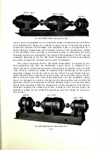
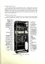
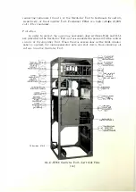
Страница 9: ...No 6 B Radio Transmitter Assembly...

Страница 10: ...60 cycles or d irect current supply of either 115 or 230 volts The piezo electric crystal controlled master oscillator and associated equip ment which is incorporated in the No 6 B Radio Transmitter...

Страница 11: ...W t i L J i I t 6 _J r f_ t rt 1 _ _J 11 r i t l 1 iJ l ft f Schematic Diagram of the No 6 B Radio Transmitter and Power Equipment F r o...

Страница 12: ...d by two motor generator sets One set KS 5320 shown above is composed of a motor driving two 2 000 volt generators One generator supplies power at 2 000 volts which is reduced by means of suitable ser...

Страница 13: ...zw i O i M3A L9A 2 0 1 zo rrl U 0 rS iz fTl or Cjt I I CJ D2A v D3A 2 0 1 0 1 zo zo I I m m U 0 U 0 r rS iz Tiz fTl m or or C i c lt z Z ID iw l DSA 2o 0 1 zo j I m U 0 U 0 rS rs Tiz Tiz m m or or c...

Страница 14: ...ng all voltag e from th e transmitter The vacuum tube circu its are prote ted by fuses a water flow relay a time delay relay and an overload l ela Control or the power supply to the entire tra nsm i...

Страница 15: ...bes V4A and V5A of the AC temperature con trol panel in the Oscillator Unit receive their power supply from the filament windings of transformer T2A The DC temperature control panel has the filament o...

Страница 16: ...y lead from terminal 5 to the grid circuits of the vacuum tubes in the Oscillator Unit Plate Power Supply Circuits The high voltage for the Oscillator Unit is obtained from the high voltage generators...

Страница 17: ...ersonnel door switches D2A and D 1 are provided in the Oscillato1 Unit and a re connected in series with the control circuits of the Amplifier Unit Vhen the rear screen door or the front window panel...

Страница 18: ...g through snap switch DlA and through terminals 1 and 2 to a fused safety switch The DC temperature control equipment is protected b v ruses Fl 1 A and Fl 2A wh i ch connect to snap swi tch IHA The co...

Страница 19: ...D AMPLIFIER GRID LEAK RESISTANCE SECOND AMPLIFIE GRID BY PASS CONDENSER No D 87738 Oscillator Unit View of Upper Shielded Compartment ANTI SING RESISTANCE SECOND AMPLIFIER t fC29A PLAT E CIRCUIT BY PA...

Страница 20: ...ance lHiA and rid current meter M2A The direct current flowing in the grid circuit is indicated by Vleter M2A marked OSCILLATOR GRI D CURRENT The plate circuit of VlA receives its DC suppl from the 2...

Страница 21: ...erminal by means of copper foil is prevented from rotating by the alignment pin The lower electrode fastens to the housing by means of the three assembly screws This assembly i s known as the No D 877...

Страница 22: ...provide connection to circuits external to the chamber The assembly consisting of the h eat insulated chamber the thermal element and the N o D 87781 Quartz Oscillator is known as the No D 86767 Cryst...

Страница 23: ..._ _ llO o D lllQ 10 PLATE VOLTAGE POTENTIOMETER TIME DELAY RESISTANCE RESIS TANCE IU Ct I t lft i RELAY CURRENT METERS FILTER CONDENSERS ft l DT 1 nr 1 o Ott Sf 1 1 SOCKET FOR 102 D VACUUM TUBE S AC T...

Страница 24: ...c vcle sing le phase AC power supply 115 volt DC pO rer su ppl or 30 volt PC pow r supply This connection H o ides power supply to the temperature control c i r cuits at all times regardless of wheth...

Страница 25: ...1A 6 0 J I C 2 1 A DllA V JA R 22 A C 20A R24A m I I I _____ I I 1 v J MS A C 22A R31A C24A I 1 2 C 25A R32A Vv V v I _ ___ _ F l lA TIA ii llOV 1 R33A Schemer tic Diagram of the AC Temperature Co11 t...

Страница 26: ...he Grid of V6A is connected th rough resistances R21A and R23A to its filament To prevent chattering and i rregular operati on of the relay the t ime delay circui t composed of condenser C21 A and res...

Страница 27: ...r r N 0 C24A 3 Ol lA F 21A R22A V6A R24A C21A R3SA V 7A C20A R36 2A R36 IA R37 2A R 37 IA Fl 2A D I A 2 Schematic Diagram of the DC Temperature Control Panel C 2SA R38A F l IA 4...

Страница 28: ...FIER GRID CURRENT The DC plate supply for V3A is supplied by the 2 000 volt generator through link switch D5A plate current meter M4A plate feed resistances Rl6 1A and Rl6 2A retardation coil L7A and...

Страница 29: ...r the filament of the No 228 A Powe Amplifier Vacuum Tube designated V4B in the Amplifier Unit is supplied at terminals 4 and i13 The filament voltage of V4B is held constant at 22 volts and is indj c...

Страница 30: ...the carrier from t his sourC No 1 00 A f _ edrolutic Filter Co ndenser No 1 00 A Filt r Cowl r1s 1 The No 1 00 A Condenser sh own aboye is of the electrolytic type T h is t pe i s userl on a coun t of...

Страница 31: ...d alongside of each other the flexible terminals of which are brought out through bushings in one of the end plate housings As installed the coils are connected in parallel by strapping terminals 1 an...

Страница 32: ...bes is obtained from the 2 000 volt terminals 17 and 5 The voltages of both 2 000 volt generators are controlled simul taneously by means of rheostat R23B the handwheel of Yhich is marked 4000 VOLT GE...

Страница 33: ...i n the plate voltage supply to the vacuum tubes Protection In 01 der to protect the operator sw itches D4B and D 5E are provided which function to sh ut down the motor generator sets whenever the re...

Страница 34: ...rn n m i lter i t wou ld be i m possibl to f iose rel ays S4 B a nd JB so t h e dan ter o r a p p iy 1 ng plat vol tage to tu bes i t h o u t he f f i ng a gr i d b i a s ol t q re i s obviated I t is...

Страница 35: ...N G R ECTIF I E R STOPPI N G CONDENSER MON ITOR I N G RECT I F I E R COU P L I N G CON DENSER DOOR 250 VOL T VOLT ME TE CIRCU IT F U SE 2 5 0 VOL T S 3 AMPERES 250 VOLT GENERATOR FUSE F 4 B 250 VOL T...

Страница 36: ...elay S4B which controls the field circuit of the high voltage generators An interval of 10 to 20 seconds is required for the time delay relay to operate thus permitting the vacuum tubes to warm u p be...

Страница 37: ...SE R S No D 877 rn Amplifier Unit Rear View of Upper Sertion SPEECH A M P L I FIER P LATE C I RC U I T RES ISTA NCE THIRD A M P L l r E R H6 I B LOAD RES ISTANCE THER MOCOUPLE FOR M 6 8 THIRD AMPL lf...

Страница 38: ...ection is afforded the vacuum tube circuits by fuses mounted in the rear of the Ampli fier Unit The code numbers and ratings of the fu es are listed in the section on Apparatus Information ANTE N NA C...

Страница 39: ...Ci i l l L J COUPLING CO NDENSER PROTECTIVE CO ILS No D 87739 Amplifier Unit Right Side View of Upper Section 1 8 ANTENNA CIRCUIT C IOB COUPL I N G CONDENSERS...

Страница 40: ...audio frequency choke coil L2B modu lator plate current meter M9B and radio frequency choke coil Ll2B The voltage is reduced to 1 500 by resistance RlOB The plate current of the modulator tube is indi...

Страница 41: ...Unit and adj usted from the front of the oscillator panel by the control marked TH I I D AjJ PLIFIER BALANC I NG CONDENSER During the neutralizing operation which ill be described later link switch D...

Страница 42: ...ked ANTENNA CURRENT Radio frequency choke coils Li 3 I B and Ll L B a re connec t ed anoss t h e coupl i ng condenser for the purpose of allowing static charges on t h e a n ten n a to ftovv to gTotmd...

Страница 43: ...a constant value before any readjustment of the thermostat is made Should either of the temperature control circuits fail to function the con tacts of the HEAT CONT RELAY should be inspected CA UTION...

Страница 44: ...d RELAY CURRENT A DJ in the clockwise direction until a maximum indi cation of relay current is obtained The relay current should be between 0 8 and 1 2 milliamperes and should cause the relay to oper...

Страница 45: ...relay SlB serves to keep the field circuits of the 2 000 volt generators open from 10 to 20 seconds after the filament voltage is applied The air escapement valve at the top of the relay and the armat...

Страница 46: ...Open t he w i ndow pa nel of the Osci llator Uni t and re move the coYe rs from t h e t wo heat i n sulated chambe rs Remo e the thermal eleme nts from the cham bers and mou n t on each element a No D...

Страница 47: ...INPUT at a mini mum The spanner wrench furnished with the Oscillator Unit is used to adjust these controls Adj ust inductance coils L4A and LlOA located in the shielded compartment accessible from the...

Страница 48: ...0 0 1 2 5 0 0 0 1 2 5 0 00 1 2 5 0 00 1 25 0 0250 0 020 0 0 1 5 0 0 1 5 l 000 WATTS 0 002 0 002 0 002 0 002 i50 0 00 1 75 0 0 0 1 7 5 0 001 i 5 0 0 0 1 7 5 5 0 0 0 0015 0 001 5 0 00 l i 5 0 0 0 1 7 5...

Страница 49: ...heostat controls located on the front of the amplifier panel should be turned in a clockwise direction for minimum generator voltage The PLATE VOLTAGE switch D3B should be OFF The water inlet and outl...

Страница 50: ...e with the frequency of the oscillator and the values of current fulfill the requi1 ements in Table IX page 47 shut down the transmitter by pushing the lower button of the MASTER CONTROL switch Open l...

Страница 51: ...rl n tnuw Pon er 1 000 watts 50 atts 500 atts Pou er A mplirier Pla te Cw nt 0 85 amp res 0 10 0 70 am peres 0 05 0 58 a m pe res 0 05 Pow A mpli tier 01dp11t Cu rrent 1 1 amperes 1 0 12 amperes 1 0...

Страница 52: ...f the anten na cu rrent t h e po er amplifier output current and the power ampl i fier plate cu rrent should h e read justed as nearly as possible to the exact alues given i n Table The ranges of cur...

Страница 53: ...at large changes in either condenser C7B or ClOB may requ ire a change in the taps on tuning inductance L7B Both taps are moved together Th is tap chang e will amount to one or two turns and must be o...

Страница 54: ...4 milliamperes as the quartz plate may be damaged The antenna current wili equal the square root of the quotient of 1 000 divided by the effective antenna resistance at the operating frequency the de...

Страница 55: ...enser Cl O B larger by 0 005 microfarad than the value given in Table IV should be used Gradually tighten the coupling by decreasing the value o f condenser C 1 OB to the approximate value given in Ta...

Страница 56: ...is as follows Pressures of different magnitudes which are established at two separate points in the Venturi Tube by the water flow in the system are transmitted through tubular connections to the meta...

Страница 57: ...ICLOSEDICLOSEDICLOSED CLOSEDICLOSEDI OPEN I OPEN OP EN OPEN OPEN CLOSE D OPEN ICLOSEDICLOSED CLOSEDICLOSE D CLOSE BOTH VALVES ON TRANSM I T T E R PIPING BY OPERAT I N G HANDLES LOCATED I N BACK OF TRA...

Страница 58: ...rnintains the pressu re in the wate1 channel A strainer is installed at the inlet to the pump to prevent foreign material which might enter into the piping system during installation or thereafter fro...

Страница 59: ...er gauge and the water circulating system should be filled until the gauge indicates that the tank is one quarter to one half full A typical diagram of a water circulating system utilizing the equipme...

Страница 60: ...on the front of the ampli fier pane The plate voltage i s appli ed by operating the top button of the PLATE VOLTAGE switch This voltage should be adj usted to 4 000 volts by varying the 4000 VOLT GENE...

Страница 61: ...ON T H E S E MACHINES AT THIS TIME Clean the oil and dust from the motor generator sets WEEKLY ROUTINE Once a week the following routine should be followed m addition to the daily routine Inspect and...

Страница 62: ...is done in accord ance with the following procedure Remove the three outer screws clamping the housing to the lower electrode In doing this care shall be taken not to separate the housing from the lo...

Страница 63: ...50 and 100 watts across a supply of direct current having a potential equal to or sl ightly greater than that of the circuit in which the condenser is used Care should be taken in doing this that the...

Страница 64: ...imes between the contacts which should be closed with a sl ight pressure on the flat sides o f the toothpick The liquid will soften any deposit that may have collected on the contacts and the rubbing...

Страница 65: ...hird amplifier the power ampl ifier or the monitoring rectifier circuit Trouble may also arise in a motor generator set for example in the motor the filament voltage generator or the grid bias voltage...

Страница 66: ...sion squeeze them towards th e center of the block Do not l e11d the cli1 s Failure of the No D 87781 Quartz Oscilla tor Should either quartz oscillator cease to operate as indicated by zero oscilla t...

Страница 67: ...eld rheostat R21 B The fa il u re of grid bias voltage w i l l cause all contro l c i rcuits to be inoperative However if voltage is i ndicated by voltmeter l 1 1 2B and the control c i rcuits fai l t...

Страница 68: ...ect il el for the transmitter is 8 db Load l111peclwzce of Power A mpli fier It is necessary that the power amplifier work into the correct load or output circuit impedance An indication of the correc...

Страница 69: ...that will enter into the quality of the radiated signal without being evident from meter readings In the event that any of the meter readings are abnormal the cause should be found and remedied In ca...

Страница 70: ...th the exception of the last item refers to various parts of the No 126 A water cooled acuum tube sorket assembly ORDERS FOR REPLACEMENT A PPA R A T U S SHOULD SPECIFY IN ADDITION TO THE I N F ORMATIO...

Страница 71: ...B I 5 i25 Ohms R Hi I A I 4 000 Ohms RBB I 44 Ohms R I 7 1 A 1 3 500 Ohms RlOB 1 88 Ohms R20 1 A 1 400 Ohms R14B I 44 Ohms R20 3A I 440 Ohms R1 7 1 B 1 1 00 000 Ohms R23A 1 1 00 Ohms R26B 1 1 0 000 Oh...

Страница 72: ...F9B FlOB F l l B F12B 3 Ampere No J l l25 3 Ampere No 9 1 125 3 Ampere No 91 125 3 Ampere No 1125 65 Ampere No 91 149 50 Ampere No 9 1 1 43 20 Ampere No 91 136 3 Ampere No 91125 3 Ampere No 91 125 2...

Страница 73: ...IA 44 R38A 935 RI7 2A 44 R39A 935 R I8A 0 67 RESISTANCES FOR NO D 87730 AMPLIFI E R UNIT Desiyn11 tion Resistan ce Oh ms esignation Resistance Ohms R2B 1 34 RI5 4B I 50 R3B 1 34 R I5 5B I 50 R4B 1 500...

Страница 74: ...ice may be obtained from the Northern E lecfric Com pany Limited and th 1 ough the I nternational Standard Electric Corporation i n other foreign counti ies Orders for replacement apparatus should spe...

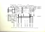
Страница 75: ...SCHEMATIC AND WIRING DIAGRAMS 69...

Страница 76: ...DIO I N PUT A M PL I FI E R 2 A M P L I F I E R 3 AM P L I F I E R POW E R A M P L I F I E R 6 5 V 2 0 0 0 V 2 50 V 4 0 0 0 V Simplified Schematic Diagram for the No 6 B Radio Tra nsmitter w M O N I T...

Страница 77: ...rF D C P lW P IPC L 1 IS 3 0 IO tr Ty UO IOQ 0 lO SNt tt IO S ll C _ _ DC R B E r E P f t L r _ r f P AL t I T lf Q i 7 E _ 1 Pio tr sCJ A 1 f_ fl 4 i I fl I 26 I r oJ k ClPP _ T TER 5 u C1 lO AG 055...

Страница 78: ...N PUT AMP L I FIER 2 P A M P L I F I E R 3 A M P L I F I E R POWE R A M P L I F I E R 6 5 v 2000V 2 50 v 4 0 0 0 v Simplified Schematic Dia gram for the No 6 B Rudio Tra nsmitter M O N I T O R _ l d...

Страница 79: ...o1 flfii i_ SIA 4 _ S2A Fl IA Fl 2A ii _ 1 l wm l J1 UI _r__ t_ __q NOTE THIS SWITCH SHOULD ALWAYS _ ycoNNECT AS SHOWN IF BE IN CLOSED POSITION TO SUPPLY L A c POWER SUPPLY IS USED A C OR D C CONTINU...

Страница 80: ...0 V A C SUPPLY 4 z 4 H P 220 V 3 A C MOTOR NO 100 A ELECTROLYTIC CONDENSER M G SET NO KS 53 20 2000 V D C GEN 2000 V D C GEN Fl F2 Fl Ol f2 M G SET NO KS 5320 2000V D C GEN 2000V DC GEN 30 WP FUSE BLO...

Страница 81: ...ER CR 4011 2 r 60 AMP P J IFAC PONER SAFETY ls1 _ w SNIT H SU 15 USED 1 To 220v 240v 3 1 1 En 50 OR60 A C ONER SLPPL Y I AMP FUSE BLOCK SWITCH SWITCH NOTE THIS SWITCH 11 L J Ll t l 1 t J 3 AMP 30 A MP...

Страница 82: ...i 3A C6A L9A DSA TO TERMINAL 38 ON AMPLIFIER UNIT TO TERMINAL 39 O N AMPLI FI ER UNIT TO TER MINAL 4 Q O N AMPLIFIER UNIT C 2iA lCrA TO TERMINAL 16 ON LL l nit r 1 1 1 AMPLIFIER UNIT D2A l v D3A 2_ 9...

Страница 83: ...1 1 1 I 1 1 I 1 I I I i I I I I I I I I I I I I I S3A RIA rr I I I I I I I I I I BLK I I L 111111 r l012A I I I 013A I J J I I I _J L_t _ _ _ _ _ _ ____ I I I __ 11 1 1 1 1 1 I L c o _ _ _ _ J j i _ _...

Страница 84: ...AMPLIF IER UNIT TO TERMINAL 39 ON AMPLIFIER UNIT TO TERMINA L 40 ON AMPLIFIER UN IT C2iA lCrA TO TERMINAL 16 ON LL t1ir r 1 AMPLIFIER UNIT 02A o o oD3A F2A d 0 l 0 l 0 l d b 0 l z o z o z o z o z o I...

Страница 85: ...R 2 1 A V4A t o R2 A C23A M9A 3 R 3 1A C 24A F l IA IA IL D I A F l 2 A R25A hV A R26A A 2 R33A R 22 A C 20A C22A D l l A R24A M IOA C25A Schematic Diagram of the AC Temperature Control Panel rr1rrr...

Страница 86: ...BL y I I L _ BR RD t 111utF C25A l I Is I Ll II D l l A 1 1 Iv r I r C20A 1 C 2 1 A 8 22A C 2 _118 I o r o tfo I Iii 0 5L l 1 1 D IOA y I I r l I o 1 1 1LE 5 1 A t t 1 t 11R 1 Jl 1 11 I r t I I 111 II...

Страница 87: ...l J 0 3 C24A R39A V6A I R 2 1 A C21A R35A D l l A R 2 2 A R 24A V 7A C20A R36 2A R36 IA R37 2A R 3 7 IA F1 2A DIA 2 Schema tic Diagram of the DC Temperature Control Panel C 25A R38A F l IA 4...

Страница 88: ...L 6 Q l lJ 1 1 1 1 1 I L A c m 0 0 1CJJ lJ r rr JI Ir 5 OR I I I I L F I YEL RED r YEL Q lJ w m M9A l_ I RED r JJ lJ JJ r l I C o OJ 1 261II I Fl il BLK BLK lJ I 1 5ftt1I z JJ r R25A I fl 10 l JJ Ill...

Страница 89: ...O TERMINAL g ON O UNn C2os If w i z 0 0 0 o 0 0 I i t i 0 _J z 0 I W J i i Z z 0 W I I i 0 0 w I I 0 I TO TERMINAL 14 ON OSC UNIT 38 5 6 w i 0 o 0 0 I 0 0 0 t I W i i Z 0 W I I i 0 I Schematic Diag am...

Страница 90: ...Z o a u t ffi if o t o 1 o Z 0 WHEN COUNTERPOISE IS USED X REMOVE LINK CONNECTING C 17 AND TERMINAL X ON C IO LINK A AND REPLACE WITH LINK C CONNECTING C 17 WITH TERMINAL l l Brr B L4 1 L4 2B r oN C...

Страница 91: ...i I i __ I I L I I I I I L____ ___ ___ _ I I I _ _ _ _ _ _ _ _ J I I I r l 11 R2B r r 1 J I I i T 1 I 1 1 i I C CP I I i I He 6 I I R5 IB l f r _t____lj I _ _ _ _l_ _J 1 4 1 J I rr m Ht1 1 2 t r 0 dt...

Страница 92: ...I I I I I I I I I I I I l f1_ _J 0 _ 1 I 1 I 1 I 1 1 1 I 1 1 1 1 1 I 1 I 1 1 1 1 1 1 1 1 I 1 I 1 1 1 I 1 1 1 l 1 I J I ASSEM on 10 ESR 306703 of th e No rrirh1f1 Dw Irn 11 D 87739 A mp ijiel Unit 85 D...

Страница 93: ...i11 11 I 11 I r I I I I I 11 I 0 CD I i j i 0r Jl W I i i i I I 1 1 I I l SSEM DET 10 I1 i ESR 308368 L _ i I1 I 1 I i I 11 I I I I 11 t f R IO BJ I R i ___ _ _ _ _ _ _ II 1 I ___s i t _ _ _ _ _ 1 II...

Страница 94: ...llustration 25 Condensers Electrolytic Filter No 1 00 A description 7 23 illustration 23 maintenance 56 C r 1 st a l 1 fp a t e r U n i t o D Rlillil dl seri pt i on 1 4 i l l u st ra t ion 1 4 i adj...

Страница 95: ...erload Relay 38 Pump No KS 3068 Water Circulating description 7 5 1 illustration 5 1 Quartz Oscillator No D 87781 adjustment 36 dl seription 1 4 illustration 1 4 maintenance 55 Radio Frequency Circuit...

Страница 96: ...F a i l u re of A n ten n a C u nen t 58 Fai l u re of F i l ament ol tage S u p p l y 60 1 F 30 3 c l i i l urt of r i d l l i a s ol l 11J 1 1 1 p p J _ 1 1 F a i l u re o f n f l S 7 7S I i u a rl...

Страница 97: ...quency 59 Failure of Antenn a Cu rren t 58 Failure of Fi lament oltage Su pply 60 1 F 30 3 c Fai l u re o f G rid Bins Vol tnge S u p pl y 60 Fai l u re of No D 8778 1 111 1 rtz Osci l l ator 59 Fail...

Отзывы: