


No. 6-B
RADIO TRANSMITTER
Instructions for Use
D
ESCRIPTION OF
A
PPARATUS
INTRO DUCTION
As the demand for better service to the broadcast listener has increased,
the use of i nadequate transmitting equi pment has largely been discontinued.
B etween the extremes of too small power on the one hand and costly h igh-power
installations on the other there is a field where the requirement is to serve well
an area of moderate size. It is for this field that the No. 6-B Radio Transmitter
is especially suitable ; it has an output of 1,000 watts capable of complete modu
l ation and requires a space comparable to previous 500-watt installations. Incor
porated in its design are the latest improvements developed by B ell Telephone
Laboratories for Western Electric Company.
The transmitter may be operated at any frequ ency from 500 to 1,500 kilo
cycles correspond ing to wave l engths from 600 to 200 meters, respectively. The
equipment is designed to operate from either alternating current supply of
three-phase, 220 volts, 50 or 60 cycles or d irect current supply of eith er 115 or
230 volts.
The p i ezo-electric crystal controll ed master oscillator and associated equ i p-
. ment which is incorporated in the No. 6-B Radio Transmitter, provides a m eans
for close maintenance of the assigned frequency at all times. The crystal is a
small quartz plate ground w ith para11el faces to a thickness which is associated
w ith the frequency of its mechanical vibration. Since this frequency is somewhat
dependent on the temperature of the crystal the latter is held at an extremely
constant temperature so that it is possible to maintain the frequency w ithin
very close l im its.
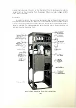
The following instructions describe the transmitter, explain the functions
of the various i ntegral parts, the theory of operation, the proper method of
adjustment, operation and maintenance, and methods of locating and correcting
troubles.
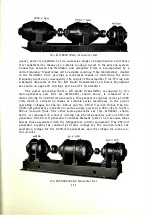
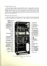
GENERAL DESCRIPTION OF APPARATUS
The No. 6-B Radio Transmitter consists of two units installed as shown
on the p receding page and on page 3. The panel unit on the left-hand side
facing
the front of the transmitter contains the crystal oscillator with its asso
ciated
circu its and temperature control equ ipment, and two stages of radio fre-
[
1
]
Содержание 6-B
Страница 1: ......
Страница 2: ...No 6 B RADIO TRANSMITTER...
Страница 4: ...No 6 B RADIO TRANSMITTER INSTRUCTIONS FOR USE Wesrern Electric Compa v Instruction Bulletin No 409...
Страница 5: ...Copyright 1930 EsTElt ELECTRIC OMPA Y I c l rintt d in U S A iv...
Страница 9: ...No 6 B Radio Transmitter Assembly...
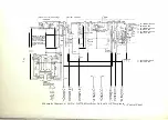
Страница 75: ...SCHEMATIC AND WIRING DIAGRAMS 69...


