


CA UTION :
T H E " PLATE VOLTAGE" S W I T C H S H O U L D g E I N T H E
" O F F "
P O S I T I O N W H E N EV E R A DJ U S T M E N T S A R E B E I N G M A D E E I T H E R I N
T H E S H I E L D E D C O M PART M E N T O F T H E O S C I LLATOR U N I T O R F RO M
T H E R E A R O F T H E A M PL I F I E R U N IT.
TUNING OF RADIO FREQUENCY C I RCUITS
No.
D-87738
Oscil!a to r Unit
The input voltage to the first amplifier is contro l l ed by condenser C4A,
whose control is marked "FIRST AMPLIFIER INPUT." Increase this con
denser a sufficient amount to enable tuning of the first ancl seconct amplifier out
put circuits. Tune the output circuit of the first ampl ifier to resonance by means
of condenser C8A marked "FIRST AMPLIFIER TUNING. " The seconct ampl i
fier output circuit is tuned by means of conctenser C 1 6A. This control is marked
"SECOND AMPLIFIER TlTNING."
NOTE :
Resonance i s i n dicated in a l l c i rc u i ts except the anten na by a n adj ustment to
m i n i m u m
plate
c
urr
ent
of
the t u be whose
output circuit is b e i n g a dj u sted.
I n the
antenna
c i rc u it resona nce i s i n d i cated
m
ax
i m
u m
a n tenna c u rrent.
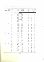
The input control condenser C4A should be adj usted until th e 1frst ampl i fier
output current meter indicates the value of current speci fied for the operating
frequency as shown on page 62.
When the plate circ uits of the first and second amplifiers are in tune with
the frequency of the oscillator, and the values of current fulfill
the
requi1·ements
in Table IX, page 47, shut down the transmitter by pushing the lower button
of the "MASTER CONTROL" switch . Open link switch D5A mounted on the
rear of plate current meter M4A. Throw triple-pole double-throw switch D4A
to the position connecting the low current thermocouple H7.2A in the output
circuit of the second amplifier, and short-circuit load resistance R17 A by clos
ing link switch D7 A. Switches D4A and D7 A are located in the left-hand
shielded compartment accessible from the rear of the Oscillator Unit.
Push the top button of the "MASTER CONTROL" switch, adj ust the
plate voltage to 4,000. Adj ust i nput control condenser C4A until meter M7 A
( Second Amplifier Output Current ) indicates a value of current within the
full scale of the meter. Adj ust "SECOND AMPLI F I E R BALANC ING CON
DENSER" ( C 12A ) u n til meter M7A indicates a minimum. ( Use spanner
wrench to adj ust condenser C 12A . )
The second ampli fier is now neutralized. Shut down the transmitter by
means of the "MAST E R CONTROL" switch. Th row triple-pole double-throw
switch D4A back to its initial position connecting the h igh current thermo
couple H7. 1A in the circuit, and open l in k switch D7 A.
No.
D-87739
A mplifier Unit
The control marked "THIRD AMPLIFIER INPUT" located on the Oscilla
tor Unit controls the input to the third amplifier as well as the output of the
transmitter. This control is adj usted, by means of the spanner wrench, to a
[
43 ]
Содержание 6-B
Страница 1: ......
Страница 2: ...No 6 B RADIO TRANSMITTER...
Страница 4: ...No 6 B RADIO TRANSMITTER INSTRUCTIONS FOR USE Wesrern Electric Compa v Instruction Bulletin No 409...
Страница 5: ...Copyright 1930 EsTElt ELECTRIC OMPA Y I c l rintt d in U S A iv...
Страница 9: ...No 6 B Radio Transmitter Assembly...
Страница 75: ...SCHEMATIC AND WIRING DIAGRAMS 69...


