


L
OCATION OF
T
ROUBLE
GENERA L
I f routine mai n tenance tests are made regularly and carefully, very few
cases of trouble will occur. To the new operator, simple troubles are often found
difficult to locate, while to th.e experienced operator, the cause is usually obvious .
It i s not possible to anticipate every case of trouble that may arise, how
ever, the time required to find the cause of any trouble wil l be reduced to a
m i n i m u m i f
a
systematic procedu re of testing is used.
Th e tra n smitter may fai l to fun ction either at the time of attempting to
start it, or it may fail while it is in operation. In either case, the procedure for
makin.g· a test is to check the circu its in the sequence they are made operative
in the process of starting the transmitter. In most cases, it is general ly possible
to immediately isolate the trouble, that is, to locate it in some one unit of the
equ i pment such as th e Motor-Generator, the Oscil lator Unit, Amplifier Unit,
th e Water C irculating System , or the Antenna System . Frequently it is possible
to sti ll furth er i solate the trouble, as for example, in the Ampl ifier U nit, it is
possible to determi n e w h ether it is in the modulator, speech amplifier, the third
amplifier, th e power ampl ifier or th e monitoring rectifier circuit. T rouble may
also arise in a motor-generator set, for example, in the motor, the filament
voltage generator or the grid bias voltage generator. Before starting on any
elaborate set of tests, check the position of all switches and controls and make
sure that they are in the correct position.
TRANSMITTER
Ove r!
oc1
ding
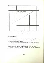
The margin of safety in designing the No. 6-B Radio Transmitter has been
made ample to allow for the proper and continued operation of this transmitter
at the rated power output of one kilowatt. It should be realized that the instan
taneous power output of the transmitter during modulation i s considerably
greater than one kilowatt. For peaks of modulation the output power may
approach four kilowatts. To assure continuity of operation and h i gh quality of
transmission, the transmitter carrier output power should under no circum
stances exceed one kilowatt.
Failure
o
f Antenna Current
If current is indicated by the output meter of the power amplifier, but
not indicated by the antenna current meter, the cause may be due to an open,
grounded or untuned antenna circuit, or to a short-circuit of the antenna
coupling condensers.
Reduced Radiation
Reduced radiation, indicated by reports from radio listeners,
.
accompanied
by reduced antenna current, usually indicates that connections in the antenna
[ 58 ]
Содержание 6-B
Страница 1: ......
Страница 2: ...No 6 B RADIO TRANSMITTER...
Страница 4: ...No 6 B RADIO TRANSMITTER INSTRUCTIONS FOR USE Wesrern Electric Compa v Instruction Bulletin No 409...
Страница 5: ...Copyright 1930 EsTElt ELECTRIC OMPA Y I c l rintt d in U S A iv...
Страница 9: ...No 6 B Radio Transmitter Assembly...
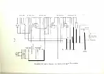
Страница 75: ...SCHEMATIC AND WIRING DIAGRAMS 69...


