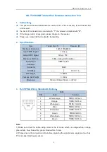
background image

15

6642-22541

Power connection 

1

2

3

4

4-position

Product marking

Direction

Description

No. 1

+DC1

Input

Supply voltage input DC1

No. 2

+DC2

Input

Supply voltage input DC2

No. 3

-COM

Input

Common

No. 4

-COM

Input

Common

This product supports redundant power connection.  The positive inputs are +DC1 and +DC2, the negative input 

for both supplies are –COM. Connect the primary voltage (e.g. +24 VDC) to the +DC1 pin and return to one of 

the –COM pins on the power input.

Connection to console port

The console port can be used to connect to the CLI  
(Command Line Interface).

The following steps needs to be taken

1.  Connect the serial diagnostic cable to the console port  

(use only Westermo cable 1211-2027). 

2.  Connect cable to your computer (USB port, if drivers are needed they can be downloaded 

from our Web page).

3.  Use a terminal emulator and connect with correct speed and format (115200, 8N1)  

to the assigned port. 

For more information about the CLI, see the WeOS management guide.

I/O connection 

Cable 1211-2027

Bottom view

Accessories
Description

Art no

Westermo console cable

1211-2027

RJ45 to DB9 cable 

1211-2210

Console port 

Position Direction* / description

No.1

In / out / GND

No. 2

Out / Tx

No. 3

In / Rx

*  Direction relative to this unit.

Содержание Wolverine DDW-142-12VDC-BP

Страница 1: ...www westermo com DDW 142 242 12VDC BP Industrial Ethernet Extender...

Страница 2: ...2 6642 22541...

Страница 3: ...and users of the Westermo products It includes information on safety and regulations a product description installation instructions and technical specifications Software tools Related software tools...

Страница 4: ...both environment and human health which could be caused by inappropriate disposal Product disposal Care recommendations Follow the care recommendations below to maintain full operation of the product...

Страница 5: ...al injuries and or damages to the product The following levels are used Warning Hazardous voltage The product must be installed by qualified service personnel and built in to an apparatus cabinet or s...

Страница 6: ...Replacing the internal fuse must only be performed by Westermo qualified personell Warning Reduce the risk of fire To reduce the risk of fire use only telecommunication line cords with a cable diamet...

Страница 7: ...uipment does cause harmful interference to radio or television reception which can be determined by turning the equipment off and on the user is encouraged to try to correct the interference by one or...

Страница 8: ...1kHz sine 2700 6000 MHz Conducted RF immunity EN 61000 4 6 Power port 10 V 80 AM 1 kHz sine 0 15 80 MHz Ethernet ports 10 V 80 AM 1 kHz sine 0 15 80 MHz SHDSL ports 10 V 80 AM 1 kHz sine 0 15 80 MHz R...

Страница 9: ...hours MIL HDBK 217F2 GB 25 C Vibration IEC 60068 2 64 random Operating 5 20 Hz 2 m s 20 500 Hz 3 dB oct 3 axis 3 30 min Shock IEC 60068 2 27 Operating 6 ms 1000 m s 6 directions 3 shocks direction Bum...

Страница 10: ...d contains amazing serial connectivity capability from being able to simulate an old AT modem convert Modbus RTU to TCP or encapsulate serial data into an IP packet DDW 142 242 12VDC BP is incredibly...

Страница 11: ...onnection Detachable screw terminal Connector size 0 2 2 5 mm AWG 24 13 Connect the product using at least 18 AWG 0 75 mm wiring Shielded cable Not required External supply current capability for prop...

Страница 12: ...ected to this port The cable shield should be properly connected 360 to an earthing point within 1 m from this port This earthing point should have a low impedance connection to the conductive enclosu...

Страница 13: ...12 V Logic zero 1V Isolation to All other Connection Detachable screw terminal Connector size 0 2 2 5 mm AWG 24 13 SHDSL Electrical specification ITU T G 991 2 Annex B Data rate 32 kbit s to 30 4 Mbit...

Страница 14: ...To Send No 8 RTS In Request To Send Female Pin 1 Pin 8 Direction relative this product Ethernet connection TX 2 ports Position Direction Description No 1 In Out Transmitted Received data No 2 In Out T...

Страница 15: ...used to connect to the CLI Command Line Interface The following steps needs to be taken 1 Connect the serial diagnostic cable to the console port use only Westermo cable 1211 2027 2 Connect cable to y...

Страница 16: ...within the product see WeOS Management Guide An external load in series with an external voltage source is required for proper functionality For voltage current ratings see Interface Specification sec...

Страница 17: ...RED LNK SHDSL ports Link indicator Port 1 2 OFF No DSL link GREEN DSL link established GREEN FLASH DSL link negotiation YELLOW Port alarm and no link Or if FRNT or RSTP mode port is blocked SHDSL port...

Страница 18: ...nside an apparatus cabinet or similar It is recommended that the DIN rail is connected to ground Snap on mounting see figure Mounting the product with integrated DIN clip Removal Removing the product...

Страница 19: ...e use of the product in full operating temperature range and service life When this product is operated at an ambient temperature above 60 C 140 F forced ventilation is required to not exceed Touch Te...

Страница 20: ...uration of the product IPConfig tool This is a custom Westermo tool used for discovery of attached Westermo products Web Configuration of the product using the web browser CLI Configuration of the pro...

Страница 21: ...set and boot as normal Go ahead with factory reset Acknowledge that you wish to conduct the factory reset by unplugging the Ethernet cable The ON LED will stop flashing This initiates the factory rese...

Страница 22: ...REV D 6642 22541 2020 06 Westermo Network Technologies AB Sweden Westermo SE 635 35 Stora Sundby Sweden Tel 46 16 42 80 00 Fax 46 16 42 80 01 E mail info westermo com www westermo com...

Отзывы: