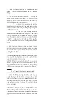
29
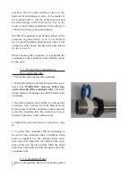
need to be lengthened. Make sure there is enough
slack in the lines for up and down travel. Connect
the hydraulic lines to the cylinder.
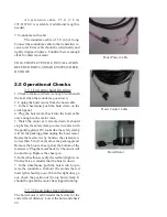
3. After the hydraulic lines are connected make
sure they are free to travel and no change to catch
on nonmoving part. The soundome cable must also
be free to travel and not catch on any nomoving
part.
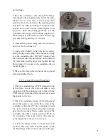
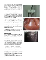
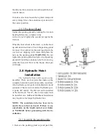
4. Install the vent screw in the reservoir. In order to
ship the hydraulic power pack full of oil the vent
screw was replaced with non-venting screw. This
non-venting screw must be removed and replaced
with the supplied venting tape.
2.7 Wiring, DC
Hydraulic Hoist
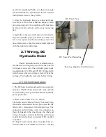
The DC hydraulic hoist is a stand alone sys-
tem that does not require power from the sonar. It
will operate on its own. The hydraulic power pack
is avialable in 12V, DC and 24V DC. Wiring is dif-
ferent between the two voltage systems. Check the
voltage of the hydraulic pack unit before wiring.
2.7.1 DC hoist board wiring
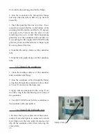
1. The DC hoist board is enclosed in its own alumi-
num box. The DC hoist board will work on both
12V hydraulic power pack units and 24V hydraulic
power pack units.
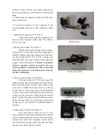
2. Hoist control cable, PN: 78.10015.0
The hoist control cable is 25 feet (7.6 meters) long.
One end is terminated witha six pin connector, the
other end is terminated with terminal lugs. The
connector end will mate with the connector on
the switch panel in the wheelhouse. the other end
will go through a strain relief fitting on the hoist
control box and connect to termintal TB1, number
to number.
If a longer hoist control cable is needed, hoist ex-
tension cables are avialable in 25 feet (7.6 meter)
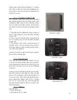
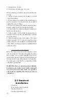
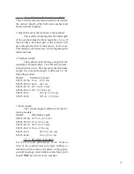
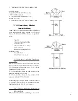
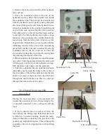
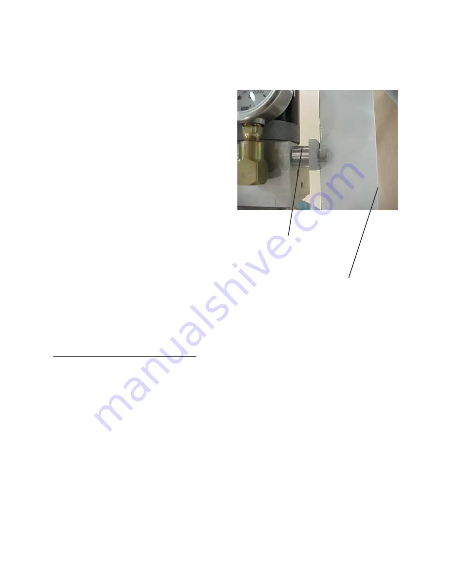
DC Power Pack Mounting
Pack Leg Opposite Limit Switches
DC Power Pack
Содержание SS395
Страница 36: ...36...

