background image

22

OPERATION

ADJUSTMENTS

CLEARING CLOGS

A clearing tool is included with your snow blower and can be mounted in the clasp on the auger housing for easy 

access. 

1. Turn the engine OFF and wait for all moving parts (wheels, impeller, auger blades, etc.) to stop moving.

2. Use the clearing tool to clear the clog.

3. Replace the clearing tool in the clasp on the auger housing.

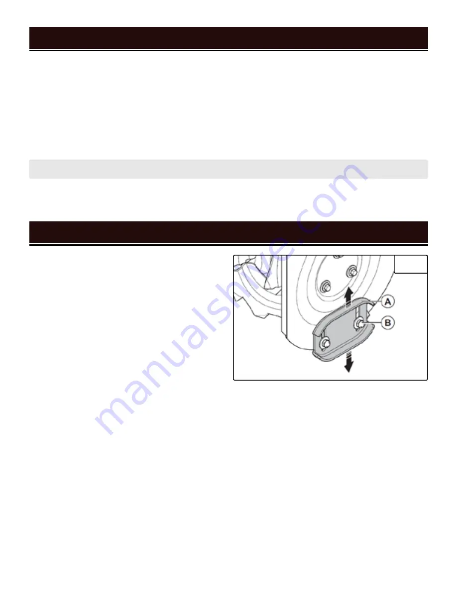
ADJUSTING THE SKID PLATES (FIG. 26)

The skid plate setting controls how far above the ground 

the scraper bar operates. When operating on concrete, 

asphalt, or other smooth surfaces, adjust the skid plate 

so that the bottom of the scraper bar rides along the 

ground. When operating on gravel, dirt, crushed rock, or 

other uneven surfaces, adjust the skid plate so that the 

bottom of the scraper bar rides just above the ground, 

to prevent debris from entering the auger. Surfaces with 

larger, coarser debris (e.g. larger pieces of gravel) re-

quire a more-raised scraper bar. 

NOTE:

 The skid plates 

are pre-adjusted for smooth surfaces from the factory.

1. Make sure the snow blower is on a smooth, level sur-

face.

2. Place a spacer board on the ground underneath the 

scraper bar, between the skid plates (A). The thickness 

of the board should be the same as the height you want 

to raise the scraper bar to. The skid plates should not 

touch the board.

3. Use a wrench to loosen the 2 nuts (B) on each skid 

plate. Let each skid plate slide down until it is flat against 

the ground.

4. Tighten the nuts and remove the spacer board.

5. Ensure the skid plates are adjusted to the same height 

on each side - this will prevent uneven wear.

WARNING!

 NEVER use your hands to clear a clog! Only use the clearing tool.

4. Run the auger for a few seconds to clear out any remaining snow or ice.

Fig. 26 

ADJUSTING THE ENGINE SPEED

For maximum efficacy while snow blowing, we rec-

ommend running the engine at (or near) maximum 

throttle. However, if for some reason you need to lower 

the engine speed, follow the instructions below.

1. The choke lever is a combination choke/throttle le-

ver. To decrease engine speed, move the choke lever to 

the right (past OPEN/RUN). To increase engine speed, 

move it back toward OPEN/RUN.

2. The engine speed is at maximum when the choke le-

ver is set to OPEN/RUN.

Содержание SB24E

Страница 1: ... trouble free performance Pay close attention to the rules for safe operation warnings and cautions If you use your tool properly and for its intended purpose you will enjoy years of safe reliable service NEED HELP CONTACT US Have product questions Need technical support Please feel free to contact us TECHSUPPORT WENPRODUCTS COM 1 800 232 1195 M F 8AM 5PM CST For replacement parts and the most up ...

Страница 2: ...justments 12 Snow Blower Preparation 15 OPERATION MAINTENANCE 18 Starting Your Snow Blower 18 Operation 20 Adjustments 22 Maintenance 23 Troubleshooting Guide 29 Exploded View Parts List 31 Warranty Statement 43 To purchase accessories for your tool visit WENPRODUCTS COM Magnetic Oil Dipstick Model No 55201 100 Foot Extension Cord Model No PC1123 50 Foot Extension Cord Model No PC5124 High Altitud...

Страница 3: ...mensions 52 5 x 25 65 x 43 9 inches 3 Engine Type 4 Stroke OHV Single Cylinder with forced air cooling system Engine Displacement 212cc Fuel Tank Capacity 0 58 gallons 2 19 L Oil Capacity 20 3 fl oz 0 6 L Runtime up to 2 75 hours Lubrication System Splash Lubrication Spark Plug Type Torch F7RTC NGK BPR7ES Spark Plug Gap 0 7 0 8 mm 0 028 0 031 inches Spark Plug Torque 18 5 22 ft lb 25 30 Nm or turn...

Страница 4: ...________ Purchased From ________________________________________________ Serial Number _________________________________________________ TO MAXIMIZE THE LIFESPAN OF YOUR SNOW BLOWER We recommend running your snow blower at least once a month for 20 to 30 minutes Start the snow blower according to the instructions and plug a small load in to make sure the outlet is producing electricity SERVICE REC...

Страница 5: ...e to all users during the entire life of the tool and review it frequently to maximize safety for both yourself and others SAVE THESE SAFETY INSTRUCTIONS SAFETY SYMBOLS The purpose of following safety symbols is to attract your attention to possible dangers The safety symbols and their explanations deserve your careful attention and understanding The safety warnings do not by themselves eliminate ...

Страница 6: ...ay have carbon monoxide poisoning WARNING RISK OF EXPLOSION HIGHLY FLAMMABLE This snow blower may emit highly flammable and explosive gasoline vapors which can cause severe burns or even death if ignited A nearby open flame can lead to explosion even if not directly in contact with gasoline Do not operate near open flame heat or any other ignition source Do not smoke near the snow blower Always op...

Страница 7: ...bels as well as those contained in this manual before attempting to assemble oper ate maintain or otherwise use your machine Keep this manual in a safe place and refer to it regularly Ensure all users of the machine are properly trained 2 Familiarize yourself with all controls and their proper operation Know how to stop the machine and disengage the controls quickly 3 Do not allow children under 1...

Страница 8: ...any other appliances that produce heat or have automatic ignitions Store the snow blower and fuel away from sparks open flames pilot lights heat and other sources of ignition 7 Do not operate the machine under the influence of alcohol drugs or other substances that could cause lack of awareness 8 Always wash hands after handling machine 9 Never direct discharge at anyone even if you think it will ...

Страница 9: ...o the power line make sure the switch is in the OFF position and the electric current is rated the same as the current stamped on the motor nameplate Running at a lower voltage will damage the motor TIP WEN offers 12 gauge outdoor rated grounded three wire extension cords in 50 foot and 100 foot lengths Model No s PC1123 PC5124 available for purchase at wenproducts com UNPACKING With the help of a...

Страница 10: ...Lower Handle Assembly 1 Flat Cotter Pin 4 total 2 spare 8mm Washer 2 10mm Washer 1 Rotator Seat 1 Screwdriver 1 Open End Wrenches 4 Chute 1 R Cotter Pin 1 Chute Rotator 1 M6x12 Bolt 8 total 2 spare Positioning Plate 3 Spring 1 Rod 1 M6 Locking Nut 8 total 2 spare Snow Blower 1 Engine Key 1 Shear Pin 2 Bowtie Clip 2 Spark Plug Wrench 1 Spark Plug Wrench Handle 1 ...

Страница 11: ...ontrols of your snow blower The components will be referred to later in the manual for assembly and operation instructions Engine Skid Plate Auger Housing Electric Start Port Recoil Start Handle Clearing Tool Drive Lever Chute Rotator Primer Button Engine Key Choke Throttle Fuel Switch Handle Scraper Bar Auger Lever Auger Cable Shift Lever Drive Cable Lower Handle Assembly Wheel Chute Oil Fill Aug...

Страница 12: ...rized with the following procedures of handling and adjusting your tool Failure to follow the safety instructions may result in serious personal injury Fig 1 Fig 2 NOTE Ensure that two knobs are installed on the left side and one on the right side upper hole as shown INSTALLING THE UPPER HANDLE FIG 2 To install the upper handle onto the lower handle you will need to used the pre installed knobs on...

Страница 13: ...ot wobble on the housing It should be securely mounted NOTE Ensure that the spiral vanes on the chute ro tator handle assembly rest in the notches on the side of the chute base NOTE Adjust the nut on the eye bolt if necessary to make it easier to assemble INSTALLING THE CHUTE ROTATOR HANDLE ASSEMBLY FIG 4 FIG 5 1 Assemble the front end of the chute rotator as shown in Fig 4 using the 10mm washers ...

Страница 14: ...w bolts to the holes on the in sides of the left and right handles A 3 Attach the cable bottle screw D to the cable screw bolts B Fig 6 Fig 8 Fig 9 Fig 7 NOTE If necessary the drive control rod s length can be adjusted The length has been set at the factory and should not require further adjustment however if you find it is absolutely necessary loosen the hex nuts adjust the bottle screw appropria...

Страница 15: ...ecked before each use or after every 8 hours of operation Follow the instructions on the next page to check the oil level TO ADD OIL 1 Place the snow blower on a level surface Make sure the engine is OFF before adding or checking oil 3 Using an oil funnel or appropriate dispenser slowly add oil into the oil fill being careful not to overfill the unit Use the dipstick to check the oil level as you ...

Страница 16: ...he snow blower performs best with ethanol free gasoline DO NOT use gasoline with over 10 ethanol The capacity of the fuel tank is 0 58 gallons Do not mix oil with gasoline TO ADD GASOLINE 1 Place the snow blower on a level surface Make sure the engine is OFF before adding or checking the fuel 2 Unscrew the fuel cap A and set it aside The fuel cap may be tight and hard to unscrew 3 Slowly add unlea...

Страница 17: ...er altitude kit Operating this snow blower without said kit may increase the engine s emissions and decrease both fuel economy and perfor mance You can order the kit at wenproducts com by searching part SB24E HA This kit should be installed by a quali fied mechanic Refer to the instructions included with your altitude kit for more information about installation WARNING To prevent serious injury fr...

Страница 18: ...to fresh air RIGHT AWAY See a doctor You may have carbon monoxide poisoning WARNING The exhaust from this product contains chemicals known to the State of California to cause cancer birth defects or other reproductive harm WARNING Do not operate snow blower near open flame or flammable materials This snow blower may emit highly flammable and explosive gasoline vapors which can cause severe burns o...

Страница 19: ...A Fig 19 A Fig 20 B A CAUTION Do not try to start the engine more than 10 times If after 10 times the engine does not start wait 40 minutes before trying again If problems persist consult the troubleshoot ing guide on p 29 If the steps in the guide do not resolve the problem call customer service at 1 800 232 1195 M F 8 5 CST iv Once the engine has started slowly return the choke lever all the way...

Страница 20: ...w the safety instructions may result in serious personal injury 20 TURNING THE SNOW BLOWER OFF 1 Release the auger and drive levers 2 Put the shift lever in the low forward position Fig 24 A 3 Run the auger for 30 60 seconds to clear out any remaining snow inside the auger housing or chute then release the auger lever 4 Turn the fuel lever to OFF This burns the fuel out of the carburetor and prolo...

Страница 21: ... pin s cir cular handle up and remove the click pin from the axle 3 Insert the click pin into the outermost hole B on the axle and flip the circular handle down This disengages the wheel from the axle and allows the wheel to rotate independently making turning much easier 4 To re engage a wheel with the axle align the hole on the hub with the hole on the axle Insert the click pin through the hub a...

Страница 22: ...ry 1 Make sure the snow blower is on a smooth level sur face 2 Place a spacer board on the ground underneath the scraper bar between the skid plates A The thickness of the board should be the same as the height you want to raise the scraper bar to The skid plates should not touch the board 3 Use a wrench to loosen the 2 nuts B on each skid plate Let each skid plate slide down until it is flat agai...

Страница 23: ...re the snow blower with fuel inside the tank for more than 2 months the fuel will go bad Run the snow blower for 20 to 30 minutes every month to maximize its lifespan Recommended Maintenance Schedule Snow Blower Every 8 Hours or Daily Every 25 Hours Every 3 Months or 50 Hours Every 6 Months or 100 Hours Before Stor age As Necessary Tires Inspect X Check Adjust Pressure X X X Impeller Auger Inspect...

Страница 24: ...p In stall a new shear pin A and bowtie clip B Your snow blower comes with two spare shear pins and two spare bowtie clips SCRAPER BAR MAINTENANCE Check the scraper bar see page 11 for excess wear if it has begun to exhibit signs of severe wear it is time to replace it Replacement scraper bars can be ordered from wenproducts com Part No SB24E 0329 Scrap er bars are a wear out part and are not cove...

Страница 25: ...ement belts can be ordered at wenproducts com Part No s SB24E 0324 SB24E 0606 Belts should be replaced by an authorized service center Contact customer service at 1 800 232 1195 M F 8 5 CST or techsupport wenproducts com for the location of the authorized service center nearest you SKID PLATE MAINTENANCE Check the skid plates for excess wear if they have begun to exhibit signs of severe wear it is...

Страница 26: ...ngine completely 4 Reinstall the oil drain bolt and tighten it securely Wipe clean any oil spillage 5 To add new oil see Step 1 Add Check Oil Fig 10 Fig 11 on page 15 SPARK PLUG MAINTENANCE Inspect and change the spark plug every 100 hours of operation refer to the Recommended Maintenance Schedule on page 23 The spark plug is important for proper engine operation Check the spark plug regularly to ...

Страница 27: ...spark plug gasket contacts the spark plug hole or 18 5 22 ft lb torque 25 30 Nm 7 Reinstall the spark plug boot over the spark plug DRAINING THE CARBURETOR Drain the carburetor after every use and before storing the snow blower refer to the Recommended Mainte nance Schedule on page 23 Draining the carburetor can help prevent build up and blockages caused by stagnant fuel inside of the carburetor 1...

Страница 28: ...zer Follow the suggested portions and instructions of your preferred stabilizer Run the engine for 15 to 20 minutes allowing the fuel stabilizer to mix with the gasoline and circulate through the carburetor and then top off with fuel Filling the fuel tank full reduces the amount of air in the tank and helps fight deterioration of fuel For Extended Periods Over 60 Days Drain the fuel tank and carbu...

Страница 29: ... service at 1 800 232 1195 M F 8 5 CST for assistance Loss of snow discharge or slowing of snow discharge 1 Chute deflector or chute is clogged 1 Shut off engine and clear clog 2 Auger is blocked 2 Shut off engine and clear blockage 3 Broken shear pin 3 Replace shear pin 4 Worn friction disc 4 Contact customer service at 1 800 232 1195 M F 8 5 CST for assistance Chute difficult to move 1 Snow or i...

Страница 30: ...rk plug boot disconnected 10 Connect spark plug boot to spark plug 11 Spark plug dirty or broken 11 Examine spark plug Clean or replace as needed 12 Electric start power cord not connected 12 Connect power cord 13 Electric start no line voltage 13 Check line voltage at power source 14 Electric start power cord gauge too low or power cord too long 14 Refer to chart on p 9 for recommended power cord...

Страница 31: ...ription Qty 32 SB24E 2032 Tube Clip 8 5mm 2 33 SB24E 2033 Fuel Tube 1 34 SB24E 2034 Governor Rod Spring 1 35 SB24E 2035 Governor Rod 1 36 SB24E 2036 Dowel Pin 10mm x 16mm 2 37 SB24E 2037 Gasket Cylinder Head 1 38 SB24E 2038 Flange Bolt M8x32 2 39 SB24E 2039 Rocker Arm Assembly Exhaust 1 40 SB24E 2040 Rocker Arm Mount 1 41 SB24E 2041 Rocker Arm Assembly Intake 1 42 SB24E 2042 Push Rod 2 43 SB24E 20...

Страница 32: ...ank Cap Assembly 1 82 SB24E 2082 Fuel Tank Assembly 1 83 SB24E 2083 Control Box Mounting Bracket 1 84 SB24E 2084 Clip 1 85 SB24E 2085 Engine Cover 1 86 SB24E 2086 Screw M4x55 2 87 SB24E 2087 Spring Washer 4mm 2 88 SB24E 2088 Flat Washer 4mm 1 89 SB24E 2089 Starter Motor 1 90 SB24E 2090 Flange Bolt M6x30 2 91 SB24E 2091 Dowel Pin 8mm x 10mm 2 92 SB24E 2092 Shroud 1 93 SB24E 2093 Oil Seal 1 94 SB24E...

Страница 33: ...EXPLODED VIEW PARTS LIST 33 ENGINE EXPLODED VIEW ...

Страница 34: ...1 Worm Gearshaft 1 1 12 SB24E 0112 Ball Bearing 16001 2Z 1 1 13 SB24E 0113 Worm Gear 1 1 14 SB24E 0114 Oil Seal 2 1 15 SB24E 0115 Left Housing 1 1 16 SB24E 0116 Woodruff Key 1 1 17 SB24E 0117 Auger Shaft 1 1 18 SB24E 0118 Right Housing 1 1 19 SB24E 0119 Bolt M5x8 1 EXPLODED VIEW PARTS LIST 34 ASSEMBLY 1 WORM HOUSING No Part No Description Qty 2 1 SB24E 0711 Knob 2 2 2 SB24E 0302 Flat Washer 8mm 2 ...

Страница 35: ... 4 3 9 SB24E 0209 Bowtie Clip 4 3 10 SB24E 0210 Flat Washer 19 5mm 4 3 11 SB24E 0211 Right Auger 2 EXPLODED VIEW PARTS LIST 35 ASSEMBLY 3 AUGER No Part No Description Qty 4 1 SB24E 0401 Driven Pulley 1 4 2 SB24E 0402 Bolt M6x12 4 4 3 SB24E 0403 Spring Washer 6mm 4 4 4 SB24E 0404 Driven Pulley Bearing Seat 2 No Part No Description Qty 4 5 SB24E 0405 Bearing 3202 2RS 1 4 6 SB24E 0406 Driven Pulley B...

Страница 36: ...314 Bolt M8x35 1 5 15 SB24E 0315 Belt Tensioner Bracket 1 5 16 SB24E 0316 Long Tension Pulley Bushing 1 No Part No Description Qty 5 17 SB24E 0317 Belt Tension Pulley 1 5 18 SB24E 0318 Short Tension Pulley Bushing 1 5 19 SB24E 0319 Bolt M10x14 1 5 20 SB24E 0320 Bolt M8x20 1 5 21 SB24E 0321 Spring Washer 8mm 1 5 22 SB24E 0322 Flat Washer 8mm 1 5 23 SB24E 0323 Auger Pulley 1 5 24 SB24E 0324 Auger Be...

Страница 37: ... Grip 2 7 5 SB24E 0705 Panel 1 7 6 SB24E 0706 Bolt M6x35 4 7 7 SB24E 0707 Nut M8 2 7 8 SB24E 0708 Left Handle 1 7 9 SB24E 0709 Nut M6 4 7 10 SB24E 0710 Lower Handle 1 7 11 SB24E 0711 Knob 3 7 12 SB24E 0712 Bent Washer 8mm 3 7 13 SB24E 0713 Lock Bolt M8x50 3 7 14 SB24E 0714 Clutch Lever Gasket 2 No Part No Description Qty 6 5 SB24E 0505 Flat Washer 6mm 6 6 6 SB24E 0506 Friction Disc Plate 2 6 7 SB2...

Страница 38: ...t 1 8 12 SB24E 0612 Pin 2 8 13 SB24E 0302 Flat Washer 8mm 1 No Part No Description Qty 8 14 SB24E 0614 Bolt M8x16 1 8 15 SB24E 0615 Shaft Bushing 2 8 16 SB24E 0616 Wheel Axle 1 8 17 SB24E 0617 Woodruff Key 1 8 18 SB24E 0618 Bolt M6x30 2 8 19 SB24E 0619 Flat Washer 6mm 2 8 20 SB24E 0620 Driven Pulley Spring 1 8 21 SB24E 0621 Wheel Housing Cover 1 8 22 SB24E 0622 Shifting Fork Bracket 1 8 23 SB24E 0...

Страница 39: ...24E 0809 Front Auger Cable Bracket 1 ASSEMBLY 9 CABLE BRACKET EXPLODED VIEW PARTS LIST 39 No Part No Description Qty 10 1 SB24E 1101 Tire 13x4 10 6 2 10 2 SB24E 1102 Wheel Pin 2 10 3 SB24E 1103 Bolt M6x12 2 10 4 SB24E 1104 Belt Cover 1 10 5 SB24E 1105 Locking Nut M8 7 10 6 SB24E 1106 Flat Washer 8mm 10 10 7 SB24E 1107 Flat Washer 19 5mm 2 10 8 SB24E 1108 Valve 2 10 9 SB24E 1109 Hub 13x4 1 6 2 10 1...

Страница 40: ...olt M10x50 1 11 10 SB24E 0910 Shifting Spring 1 11 11 SB24E 0911 Upper Shifter Rod 1 No Part No Description Qty 11 12 SB24E 0912 Wheel Clutch Cable 1 11 13 SB24E 0913 Auger Clutch Cable 1 11 14 SB24E 0914 Nut M8 1 11 15 SB24E 0915 Shifter Rod Bottle Screw 1 11 16 SB24E 0916 Bolt M8 1 11 17 SB24E 0917 Lower Shifter Rod 1 11 18 SB24E 0918 Pin 1 11 19 SB24E 0919 Flat Washer 13 5mm 1 11 20 SB24E 0920 ...

Страница 41: ... 10 SB24E 1010 Driving Pulley Wheels 1 12 11 SB24E 1011 Engine Assembly 1 No Part No Description Qty 12 12 SB24E 1012 Shield 1 12 13 SB24E 1013 Bolt M6x12 1 12 14 SB24E 1014 Nut M8 1 12 15 SB24E 1015 Bolt M8x12 1 12 16 SB24E 1016 Tension Pulley Spring 1 12 17 SB24E 1017 Bolt M8x25 2 12 18 SB24E 1018 Belt Guide 1 12 19 SB24E 1019 Bolt M8x16 1 12 20 SB24E 1020 Driving Pulley Washer 1 12 21 SB24E 102...

Страница 42: ...te Base Plate 1 13 8 SB24E 1308 Rotator Handle Eye Bolt 1 13 9 SB24E 1309 Nut M8 1 13 10 SB24E 1310 Bent Washer 8mm 2 ASSEMBLY 13 CHUTE ROTATOR No Part No Description Qty 13 11 SB24E 1311 Rod 1 13 12 SB24E 1312 Flat Washer M6 1 13 13 SB24E 1313 Bolt M6x12 1 13 14 SB24E 1314 Rotator Handle Grip 1 13 15 SB24E 0711 Knob 1 13 16 SB24E 1316 Bushing 1 13 17 SB24E 1317 Nut M6 6 13 18 SB24E 1318 Positioni...

Страница 43: ...be sent to WEN before the replace ments can be shipped out Upon the confirmation of a WEN representative your product may qualify for repairs and service work When re turning a product for warranty service the shipping charges must be prepaid by the purchaser The product must be shipped in its original container or an equivalent properly packed to withstand the hazards of shipment The product must...

Страница 44: ...THANKS FOR REMEMBERING v 2019 08 13 ...

Отзывы: