WEB-2000
User’s
manual
8
2.1
The
Front
and
Rear
panels
of
the
WEB-2000
You
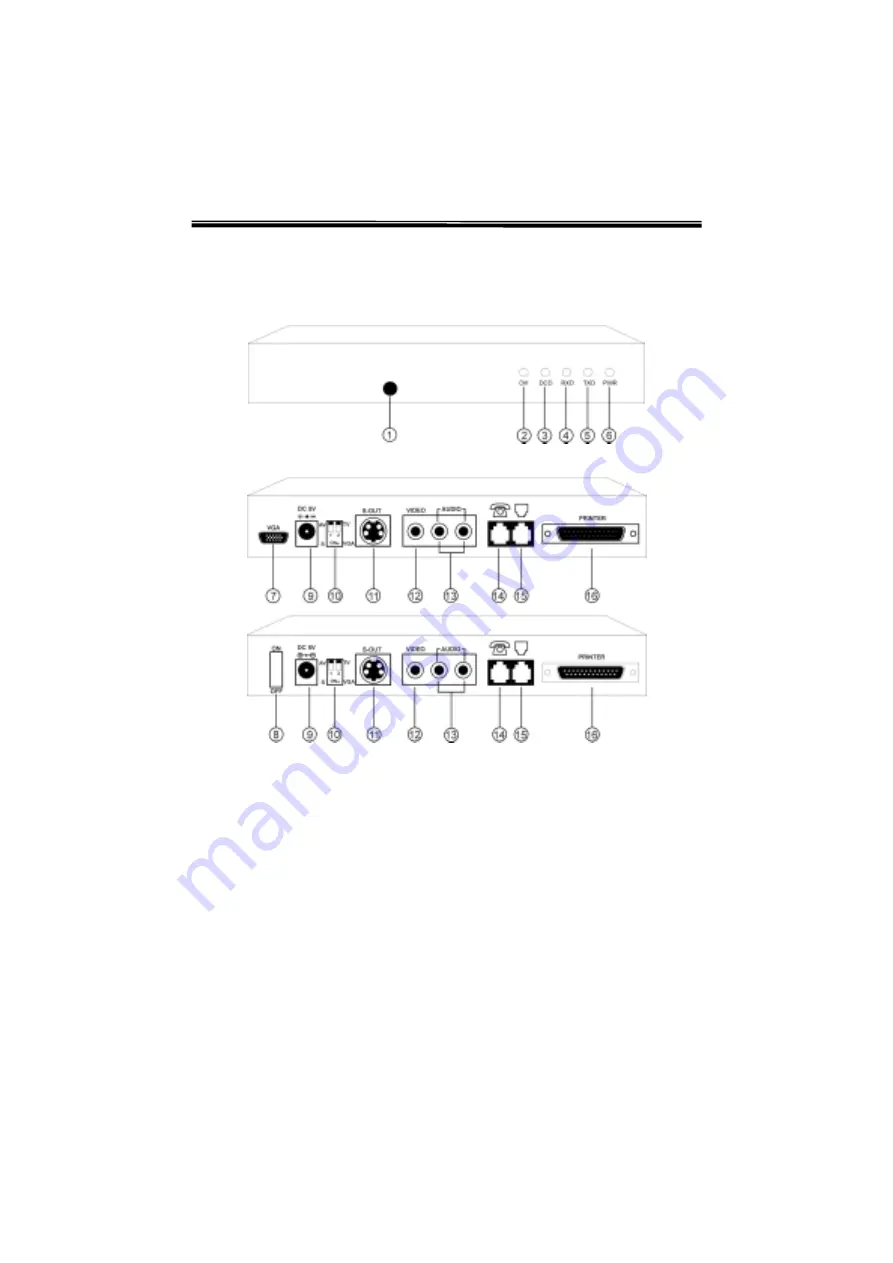
may refer to Figure 2-1 for the configuration of the front panel. Figure 2-2 shows
the
rear panel configuration of the two different models. One with a VGA port
(
Model
1
)
and the other one with a power on/off switch (
Model
2
).
Figure
2-1
The
Front
Panel
of
the
WEB-2000
Figure
2-2
The
Rear
Panel
of
the
WEB-2000
1.
Remote Control IR receiver
9. DC power adapter port
2.
OH – off hook LED
10.
DIP switch
3.
DCD – data carrier detect LED
11.
S-VIDEO output
4.
RXD – data reception LED
12.
VIDEO output
5.
TXD – data transmission LED
13.
AUDIO output
6.
PWR – power on/off LED
14.
Phone line-out
7.
VGA – VGA monitor port
15.
Phone line-in
8.
Power switch On/Off
16.
PRINTER port (Canon BJP color
printer)
Model
1
Model
2


