Weir SPM QWS 2500 XL Скачать руководство пользователя страница 42


42 of 44 

Document P/N: 

2P137414 

Release Date: 

05/29/2017 

Revision: IR 

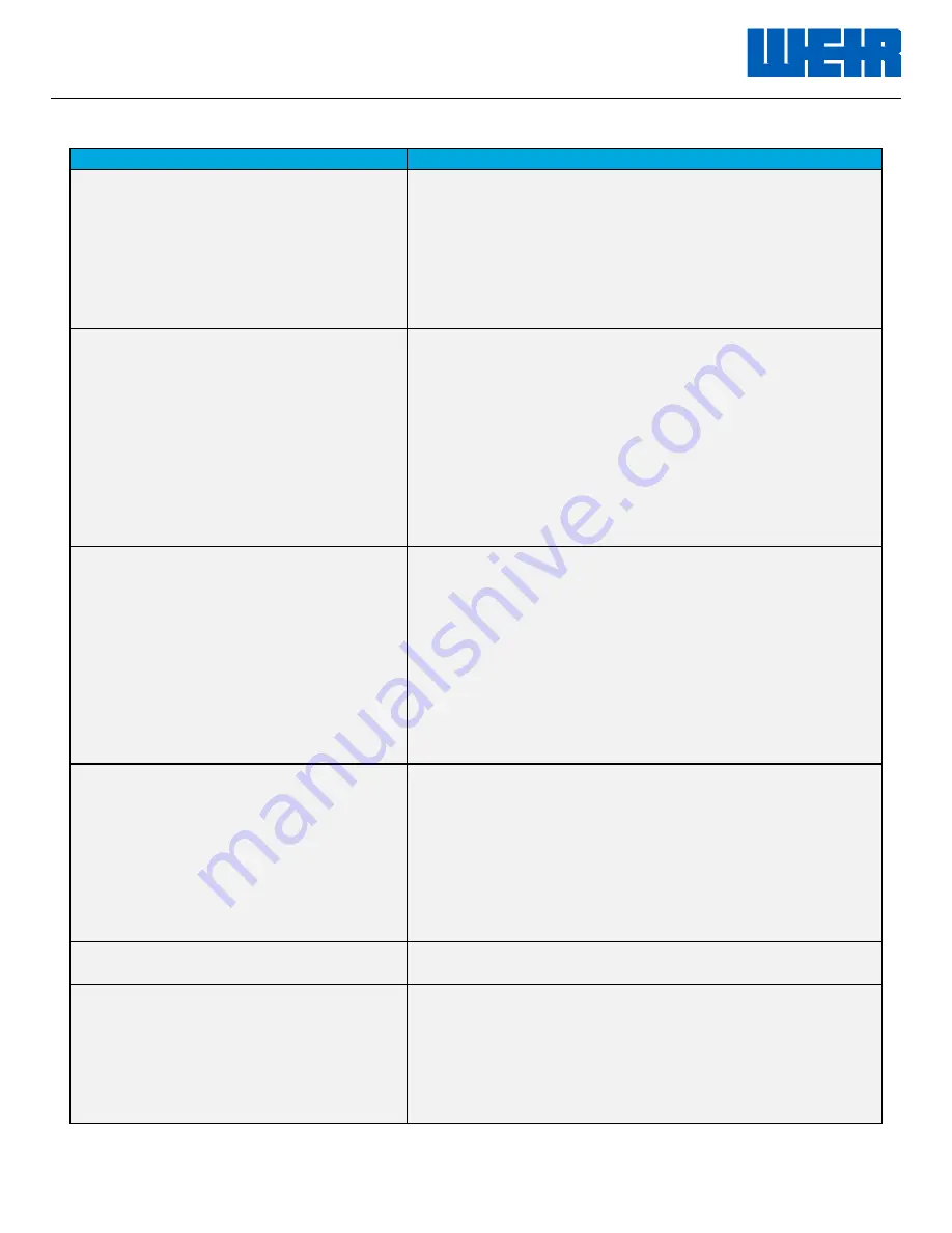
Troubleshooting Guide: 

TROUBLE SYMPTOM: 

PROBABLE CAUSE: 

A.) 

Abnormally high vacuum at power 
end lube pump suction inlet (may 
or may not be accompanied by 
abnormally low oil pressure). 

1.  Extremely cold ambient temperature/dangerously high 

oil viscosity. 

2.  Clogged lube system suction strainer. 
3.  Kinked or collapsed lube system suction hose. 
4.  Clogged oil reservoir breather. 
5.  Erroneous gauge reading. 
6. Closed tank valve. 
 

B.) 

Abnormally low power end lube oil 
pressure with normal to low 
vacuum reading at lube pump 
suction (may or may not be 
accompanied by high oil 
temperature). 


1.  Leak in lube pump suction piping, which allows air to be 

drawn into the system. 

2.  Worn or damaged lube pump. 
3.  Leak in lube pump pressure piping. 
4.  Low oil level in reservoir. 
5.  Clogged oil filter element. 
6.  Faulty lube system relief valve. 
7.  Extremely hot lube oil temperature/dangerously low oil 

viscosity. 

8.  Erroneous gauge reading. 
 

C.) 

Abnormally high power end lube 
oil temperature (may or may not 
be accompanied by low oil 
pressure). 


1.  Extremely warm ambient temperature/dangerously low 

oil viscosity/incorrect grade of gear oil. 

2.  Gear oil contaminated with water, trash, or air bubbles. 
3.  Plunger pump has been operated continuously for too 

long a period of time at or near its maximum horsepower 
or torque rating. 

4.  Heat exchanger or oil cooler malfunction. 
5.  Erroneous gauge reading. 
6.  Internal power end damage or power end wear. 
7.  Thermostatic valve malfunction. 
 

D.) 

Leaking power end oil seals. 


1.  Extremely cold ambient temperature/high oil viscosity. 
2.  Damaged seal surface on mating parts. 
3.  Clogged oil breather/high crankcase pressure. 
4.  Worn or damaged seal. 
5.  Contaminated lube oil. 
6.   Loose inspection cover bolts, torn inspection cover 

gaskets, or sealing bonded inspection cover bolt 
washers. 


E.)        Leaking lube lines. 

1.   Loose fittings, damaged hoses, damaged fittings. 

F.) 

Leaking fluid end seals. 

1.  Seal installed improperly. 
2.  Seal cut or pinched on installation. 
3.  Mating seal surface not cleaned properly prior to seal 

installation. 

4.  Damaged or corroded mating seal surface. 
5.  Sealing part not properly tightened. 
 

Содержание SPM QWS 2500 XL

Страница 1: ... copyright owner SPM SAFETY IRON SAFETY HAMMER SUR DROP DESTINY STAMPEDE DURALAST and GLADIATOR are trademarks and or registered trademarks of S P M Flow Control Inc WEIR and WEIR logo are trademarks and or registered trademarks of Weir Engineering Services Limited Certain features of some of the products disclosed in this document may be protected worldwide by patents pending and registered in th...

Страница 2: ...ide adequate guarding around the fluid end as well as the inlet and discharge piping to protect against burn injury A SPM well service pump operates at very high pressure and features some external moving parts It is the customer s responsibility to provide adequate warning and protection for personnel for when the unit is operated All images and drawings shown in this document are for representat...

Страница 3: ...as been pressured beyond its specified working pressure should be returned to Weir Oil Gas for disassembly inspection and recertification 6 Welding brazing or heating any part of the pump with the exception of driveline companion flanges is prohibited If accessories must be attached consult Weir Oil Gas factory prior to installation 7 The SPM pump suction supply flow and pressure minimums in the p...

Страница 4: ...atures are anticipated the fluid cylinder must be completely drained of any fluid Failure to do this may result in fluid cylinder damage from fluids which have hardened or frozen 3 All SPM threaded components are right hand threaded unless specifically designated otherwise Any turning counterclockwise will unscrew the assembly Always make sure any threaded component is made up properly with the pr...

Страница 5: ...ting in any area must be returned to Weir Oil Gas for repair and recertification prior to operating again 6 All fluid cylinders in operation must be disassembled and inspected for cracks Fluid cylinder inspection should occur on a monthly basis or every 100 hours of operation The operation of any pump with even small surface cracks in any area of the fluid cylinder can result in equipment failure ...

Страница 6: ...GE INSTALLATION 20 POWER END LUBE SYSTEM REQUIREMENTS 25 POWER END LUBE SYSTEM SCHEMATIC 28 POWER END LUBE STARTUP AND PERFORMANCE DATA 28 TACH DRIVE RATE METER CALIBRATION SPECIFICATIONS 31 STARTUP AND BREAK IN PROCEDURE 32 SECTION III MAINTENANCE AND REPAIR 36 ROUTINE PREVENTATIVE MAINTENANCE 36 SPM QWS 2500 DURALAST FLUID END REMOVAL 38 SPM QWS 2500 GROOVED AND GROOVELESS FLUID END REMOVAL 39 F...

Страница 7: ...oad pounds RPM Crankshaft revolutions per minute SL Stroke length inches T Torque foot pounds Pump Data Formulas To calculate the HHP output when the volume and pressure are known GPM x PSI HHP 1714 To calculate the BHP input required when the volume pressure and mechanical efficiency are known GPM x PSI BHP 1714 x ME To calculate the maximum possible pressure when the BHP flow and ME are known BH...

Страница 8: ... required to maintain a specified flow velocity when the GPM and desired flow velocity are known GPM x 3208 Internal Area Required FV To calculate the maximum allowable GPM through a specified hose or pipe at a specified flow velocity when the internal area of the pipe and the desired flow velocity are known FV x A Max GPM 3208 To calculate pinion shaft or driveline torque when the input BHP and p...

Страница 9: ...with diesel or light oil When pumps are shipped by ocean cargo care should be taken to crate the pump in a watertight container and ship below deck to prevent salt water contamination Care should be taken to prepare the pump for possible long term storage New pumps are not prepared for long periods of storage and should be put in service as soon as possible Follow the SPM preservation guide for pu...

Страница 10: ...ty well service applications such as acidizing fracturing well killing etc Optional packing assemblies valve assemblies discharge flanges suction manifolds etc are available for a wide variety of unitization arrangements for the pumping of various specific fluids and for service in a wide range of ambient conditions The weight of the pump will vary slightly depending on plunger size and other opti...

Страница 11: ...lity Induction hardened gear teeth Supported by two 2 heavy duty spherical roller bearings mounted in removable replaceable bearing carriers Gear Ratio 6 353 1 ratio allows direct drive from a 1900 to 2100 RPM diesel engine powershift transmission without over speeding the pump Pony Rods Replaceable type w clamp connection at plunger end Machined from steel Precision ground hard overlay seal surfa...

Страница 12: ...12 of 44 Document P N 2P137414 Release Date 05 29 2017 Revision IR Performance Data ...

Страница 13: ...13 of 44 Document P N 2P137414 Release Date 05 29 2017 Revision IR ...

Страница 14: ...14 of 44 Document P N 2P137414 Release Date 05 29 2017 Revision IR ...

Страница 15: ...15 of 44 Document P N 2P137414 Release Date 05 29 2017 Revision IR ...

Страница 16: ...16 of 44 Document P N 2P137414 Release Date 05 29 2017 Revision IR ...

Страница 17: ...17 of 44 Document P N 2P137414 Release Date 05 29 2017 Revision IR ...

Страница 18: ...18 of 44 Document P N 2P137414 Release Date 05 29 2017 Revision IR ...

Страница 19: ...void over pressuring the pump when operating in low gear or converter mode The mechanical driveline should have a Diesel Engine Use torque rating of 20 000 ft lbs 96 000 ft lbs Short Duration and should have no less than 1 slip capacity Weir Oil and Gas recommends a maximum driveline angle of 3 degrees Power End Mounting The pump must be securely bolted to the skid or vehicle at all four power end...

Страница 20: ...FLUID END ASSEMBLY WITHOUT USING EQUIPMENT RATED FOR THIS LOAD CAN CAUSE EQUIPMENT DAMAGE PERSONAL INJURY OR DEATH WARNING DO NOT HANDLE LIFT INSTALL OPERATE OR MAINTAIN THIS SPM PUMP WITHOUT READING THIS OPERATION INSTRUCTION AND SERVICE MANUAL THOROUGHLY TRAINING IN THESE DOCUMENTS IS A MUST FOR PACKAGERS OPERATIONS AND MAINTENANCE PERSONNEL FAILURE TO DO SO CAN LEAD TO SERIOUS INJURY DEATH EQUI...

Страница 21: ...nage and a secure work location when performing this operation 1 Thoroughly clean all mating surfaces of both the flange and the pinion shaft ensuring that the faces are free of debris and damage that might impede smooth installation Remove any burrs or corrosion 2 Lubricate the mating surfaces with suitable grease 3 Access to a pressured water hose connection should be available 4 Using good prac...

Страница 22: ...22 of 44 Document P N 2P137414 Release Date 05 29 2017 Revision IR ...

Страница 23: ...23 of 44 Document P N 2P137414 Release Date 05 29 2017 Revision IR ...

Страница 24: ...BTAIN OPTIMUM PERFORMANCE REGARDLESS OF THE POWER END LUBRICANT SELECTED THE LUBRICANT TARGET OPERATING TEMPERATURE SHALL STAY BELOW 160 F General Service Power End Lubricants Gear oil must have the following properties 1 Viscosity rating of ISO 220 2 Rated for extreme pressure EP service 3 Viscosity Index of 100 or higher 4 Pour point of 00 F 17 70 C or lower 5 Timken Test rating of 50 lbs or hig...

Страница 25: ... E A serviceable magnet located near the 3 return port is highly recommended F Breather filler cap to be 40 micron 25CFM minimum and should include a built in strainer to prevent trash from entering the reservoir G Dipstick or sight glass to indicate oil level in the reservoir H Reservoir must be located below the lowest drain port in the plunger pump and as near the plunger pump as possible prefe...

Страница 26: ...imum working pressure of 800 PSI C The oil filter must be rated at 50 GPM 200 PSI minimum must have a built in 15 to 25 PSI relief valve and 25 to 40 micron elements The filter should be a canister enclosed throw away element type The Parker 60 series filter is widely used and acceptable The filter must be located in an easily serviceable location and a built in bypass indicator service indicator ...

Страница 27: ...e and should be located down stream from the oil filter The cooler should be rated at 80 GPM 300 PSI minimum and should have 2 minimum inlet and outlet connections If the well service unit will also be subjected to periods of cold weather the oil cooler must be plumbed in a manner that will allow the oil to bypass the cooler when cold ambient conditions occur B In extremely cold ambient conditions...

Страница 28: ...28 of 44 Document P N 2P137414 Release Date 05 29 2017 Revision IR Power End Lube System Schematic ...

Страница 29: ... minutes to purge the system of air Stop the engine and add oil to the reservoir in order to bring it back to the full level C With the transmission in neutral restart the engine Increase engine RPM up to full RPM gradually while monitoring both the vacuum gauge at the lube pump suction inlet and the pressure gauge at the plunger pump lube inlet If the lube oil is warm enough and thin enough the v...

Страница 30: ...re and pressure readings during full horsepower or full torque plunger pump operation The system specifications herein should be observed in addition to each unit s normal system characteristics after having been put into service Deviations from normal in any unit s system is an important factor in spotting potential problems and avoiding power end damage due to insufficient lubrication Maximum Ac...

Страница 31: ... 0 00775 1 2316 0 3425 0 00816 1 2964 4 1 2 114 3 0 4118 0 00981 1 5587 0 4335 0 01032 1 6408 5 127 0 0 5084 0 01211 1 9244 0 5352 0 01274 2 0257 5 1 2 139 7 0 6152 0 01465 2 3285 0 6476 0 01542 2 4510 NOTE THE VOLUMETRIC EFFICIENCY AND RESULTING DISPLACEMENT WILL VARY SLIGHTLY DUE TO OPERATIONAL FACTORS SUCH AS PUMP SPEED SUPERCHARGE CONDITIONS AND THE SPECIFIC GRAVITY OF THE FLUID BEING PUMPED V...

Страница 32: ...nd all piping connections are tight 7 Check to see that the power end lube system startup adjustments and plunger lube system startup adjustments have been performed 8 Check to see that the suction pulsation dampener has been charged properly 9 Check to see that the primary suction piping is connected to an adequate supply of cool clean water for testing Check to see that all connections are tight...

Страница 33: ... such as elapsed time ambient temperature power end lube oil temperature power end lube oil pressure supercharge pressure etc After returning the engine to idle and transmission to neutral physically inspect the plunger pump before proceeding further D Break In Procedure 1 Adjust the test choke engine and transmission to obtain approximately the values in the table below These settings should be a...

Страница 34: ...etc After returning the engine to idle and the transmission to neutral physically inspect the plunger pump before proceeding further 3 Adjust the test choke engine and transmission to obtain the values in the table below horsepower These settings should be approximately as follows PLUNGER DIAMETER IN MM INPUT SPEED PINION PUMP RPM POWER BHP KW PRESSURE PSI MPA FLOW RATE GPM BPM LPM 3 3 4 95 3 889 ...

Страница 35: ...closely observe the plunger pump for any unusual noise vibration fluid leaks and oil leaks Record all pertinent information such as elapsed time ambient temperature power end lube oil temperature power end lube oil pressure supercharge pressure etc Return the engine to idle the transmission to neutral and stop shut down the engine 5 Visually inspect the power end for oil leaks around the pony rod ...

Страница 36: ... and fluid end attachment nuts Discharge Flanges Companion Flange Packing Nuts Retainer and Discharge Nuts If the suction stabilizer has a nitrogen filled bladder check the nitrogen charge pressure and correct as needed Follow the manufacturer s charging pressure recommendations usually 60 80 of suction inlet pressure Weekly Preventive Maintenance Check all items on daily list Check all valves ins...

Страница 37: ... shell bearings Retorque connecting rod housing bolts to correct torque value It is difficult to assess wear and tear on a pump based solely on hours operated due to the variations in duty cycle and types of service However roller bearings rod bearings and gearing may need replacing after approximately 1200 to 3000 hours With either component signs of extensive wear will generally show up as spall...

Страница 38: ...ead hoist 5 Ton minimum capacity to prevent Fluid End from falling off the Power End See Lifting Requirements section Remove the slack from the lifting chains 3 Using a 23 4 wrench remove the twenty 13 4 nuts which secure the fluid cylinder to the power end stay rods Remove the fluid cylinder from the power end 4 Set the fluid end on a pallet up right 5 Inspect the face of the fluid cylinder for w...

Страница 39: ... Using a 2 wrench remove the twenty 1 nuts which secure the fluid cylinder to the power end stay rods Remove the fluid cylinder from the power end and set fluid end on pallet upright 4 Inspect the face of the fluid cylinder for wear or fretting around the stay rod holes Inspect the shoulders of the stay rods for wear or cracks Check all twenty stay rod nuts for the correct torque 1000 ft lbs with ...

Страница 40: ...and install the nuts hand tight Nuts are tightened to 2000 lb ft for both styles The tightening increments are 1 3 2 3 and full value in the pattern outlined in the SPM QWS 2500 fluid end operation instruction and service manual SPM document number 2P136539 Inspection of the stay rods in the field can determine if a pump has damaged stay rods Weir recommends that when you replace one stay rod you ...

Страница 41: ...h remove the three 1 4 capscrews and 1 4 washers which retain the pony rod seal Inspect the double lip pony rod oil seal for damaged worn or hardened non pliable sealing lips and replace the seal if necessary 4 Cut the tie wire which is laced through the six 3 4 socket head capscrews that secure the pony rod to the crosshead Using a 5 8 hex key wrench remove the six 3 4 socket head capscrews Remov...

Страница 42: ... Abnormally high power end lube oil temperature may or may not be accompanied by low oil pressure 1 Extremely warm ambient temperature dangerously low oil viscosity incorrect grade of gear oil 2 Gear oil contaminated with water trash or air bubbles 3 Plunger pump has been operated continuously for too long a period of time at or near its maximum horsepower or torque rating 4 Heat exchanger or oil ...

Страница 43: ...loose worn or damaged connections 2 Air entering supercharge system through leaking charge pump seals 3 Fluid being pumped contains gas or vapor 4 Insufficient supercharge flow or pressure 5 Valve cocked open broken valve spring or valve stop 6 Worn or damaged valve valve insert or valve seat 7 Improperly charged or ineffective suction pulsation dampener I Low discharge pressure rough running pump...

Страница 44: ... the original shipping date Returned parts must be shipped prepaid to the appropriate address including a copy of the original invoice or delivery ticket Please refer to our web site for global locations Weir Oil Gas 601 Weir Way Fort Worth TX 76108 USA Tel 1 800 342 7458 Fax 817 977 2508 www global weir Copyright 2017 S P M Flow Control Inc All rights reserved S P M Flow Control Inc is the owner ...

Отзывы: