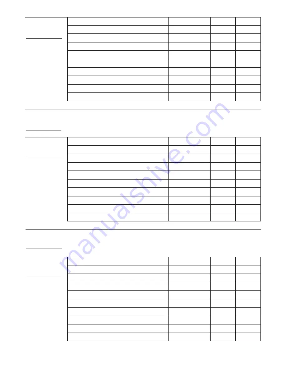
Weider Pro 8000 Скачать руководство пользователя страница 34

34

MONDAY

Date:

/

/

EXERCISE

WEIGHT

SETS

REPS

EXERCISE

WEIGHT

SETS

REPS

EXERCISE

WEIGHT

SETS

REPS

AEROBIC EXERCISE

AEROBIC EXERCISE

TUESDAY

Date:

/

/

WEDNESDAY

Date:

/

/

THURSDAY

Date:

/

/

FRIDAY

Date:

/

/

Make photocopies of this page for scheduling and recording your workouts.

Содержание Pro 8000

Страница 1: ...ber in the space above for reference Serial Number Decal under seat QUESTIONS As a manufacturer we are com mitted to providing complete customer satisfaction If you have questions or if there are miss...

Страница 2: ...RT IDENTIFICATION CHART and a PART LIST EXPLODED DRAWING are attached in the center of this manual Remove the PART IDENTIFICATION CHART and PART LIST EXPLODED DRAWING before begin ning assembly TABLE...

Страница 3: ...the pul leys at all times If the cables bind as you are exercising stop immediately and make sure that the cables are on the pulleys Replace all cables at least every two years 11 Always stand on the...

Страница 4: ...r goal is to tone your body build dramatic muscle size and strength or improve your cardiovascular sys tem the weight system will help you to achieve the specific results you want For your benefit rea...

Страница 5: ...plenty of time and by deciding to make the task enjoyable assembly will go smoothly You may want to assemble the weight system over a couple of evenings Select a Location for the Weight System Becaus...

Страница 6: ...3 and the Left Base 2 to the Right Base 1 with two M8 x 83mm Bolts 89 and two M8 Nylon Locknuts 115 Do not tight en the Locknuts yet 2 Insert four M8 x 75mm Carriage Bolts 84 up through the Left Base...

Страница 7: ...75mm Carriage Bolts 84 and two M8 Nylon Locknuts 115 Do not tighten the Locknuts yet 6 Attach the Right Upright 4 to the Right Base 1 with the two indicated M8 x 75mm Carriage Bolts 84 and two M8 Nylo...

Страница 8: ...he Locknuts yet 9 Attach the Left Top Frame 8 to the Left Upright 5 with two M8 x 83mm Bolts 89 the Left Upright Plate 37 and two M8 Nylon Locknuts 115 Note The Left Upright Plate is wider than the Re...

Страница 9: ...holes on the indicated side onto the Weight Guides Press a Weight Tube Bumper 66 into the Long Weight Tube 36 Orient the Weight Tube as shown Insert the Weight Tube into the stack of Weights 35 Grease...

Страница 10: ...n the same manner 12 Attach the Right Top Frame 7 to the Right Upright 4 with two M8 x 80mm Bolts 94 two M8 Washers 117 and two M8 Nylon Locknuts 115 Do not tighten the Locknuts yet Attach the Right T...

Страница 11: ...14 13 7 4 117 115 115 22 91 116 116 24 82 24 25 132 124 124 82 7 94 117 117 25 15 10 94 115 117 117 115 115 115 5 84 2 15 Attach the Left Seat Frame 10 to the Left Base 2 with the two indicated M8 x 7...

Страница 12: ...knut 114 Make sure the decal on the Foot Plate is right side up Do not overtighten the Locknut the Foot Plate must be able to pivot easily 18 Remove the M10 x 45mm Button Bolt 105 from a Press Arm 14...

Страница 13: ...o not overtighten the Locknut the Dip Assist Latch must be able to pivot easily Engage the Latch over the rod on the Rear Upright 6 22 Wet the lower end of the Left Butterfly Arm 18 with soapy water S...

Страница 14: ...e cables and to identify the cables Locate the Lat Cable 71 Route the Cable up through the Right Top Frame 7 and over a 90mm Pulley 39 Make sure the Cable is between the Pulley and the rod in the Top...

Страница 15: ...acket on the Rear Upright 6 with an M8 x 22mm Shoulder Bolt 88 and an M8 Nylon Locknut 115 Make sure the flat edge of the Cable is against the bracket 31 Locate the Ab Cable 72 Wrap the Cable over a 9...

Страница 16: ...he Cable in the groove of the Pulley 35 Wrap the Ab Cable 72 around a V pulley 40 Attach the V pulley a Cable Trap 49 an M10 Washer 116 and two Full Finger Guards 43 to the Right Upright 4 with an M10...

Страница 17: ...Spacers 75 and an M10 Nylon Locknut 114 39 Attach a 90mm Pulley 39 inside the Right Seat Frame 9 over the Leg Lever Cable 70 with an M10 x 45mm Bolt 138 and an M10 Nylon Locknut 114 40 Route the Leg...

Страница 18: ...8mm Bolt 101 and an M10 Nylon Locknut 114 Make sure the Finger Guards are on the outside of the U bracket 45 Wrap the Leg Lever Cable 70 under a 90mm Pulley 39 Attach the Pulley a Small Cable Trap 48...

Страница 19: ...in the indicated U bracket 50 with an M10 x 52mm Bolt 102 and an M10 Nylon Locknut 114 Make sure the Cable Trap is ori ented to hold the Cable in the groove of the Pulley 51 Wrap the Right Stack Cabl...

Страница 20: ...hread an M12 Nut 128 all the way onto the Right Stack Cable 68 Thread the Right Stack Cable 68 into the Long Weight Tube 36 Tighten the M12 Nut 128 against the M12 Washer 129 55 Locate the Press Cable...

Страница 21: ...and an M10 Washer 116 to the Press Frame 13 with an M10 x 135mm Bolt 98 Make sure the Cable Trap is oriented to hold the Cable in the groove of the Pulley 60 Wrap the Press Cable 69 around a V pulley...

Страница 22: ...8 Nylon Locknut 115 Note Do not complete ly tighten the Locknut it should be tightened so that only two threads of the Cable show past the Locknut as shown in the inset draw ing 65 Attach the Right Ba...

Страница 23: ...8 Washer 117 and an M8 Nylon Locknut 115 Do not overtighten the Locknut the Lock Plate must be able to pivot easily Attach the Leg Pin 83 to the Right Seat Frame 9 with an M4 x 16mm Self tapping Screw...

Страница 24: ...to the Front Shrouds 15 143 not shown and Rear Shrouds 25 in the same manner 70 135 135 135 44 25 26 109 132 132 7 141 142 1 26 109 132 132 15 71 Make sure that all parts have been properly tightened...

Страница 25: ...eys the amount of resistance at each exercise station may vary from the weight setting Use the WEIGHT RESISTANCE CHART on page 27 to find the approximate amount of resistance at each weight station AT...

Страница 26: ...to the desired position Reengage the Knob into the Left Upright and the Backrest Frame 27 Make sure the Knob is fully tightened 27 121 LOCKING THE DIP ASSIST Make sure the Dip Assist 21 is locked when...

Страница 27: ...station may vary due to differences in individual weight plates as well as friction between the cables pulleys and weight guides WEIGHT Top 1 2 3 4 5 6 7 8 9 10 HIGH PULLEY lbs 15 30 44 60 74 87 99 1...

Страница 28: ...Cable 71 and the Ab Cable 72 Use the diagram to make sure that the cables and the cable traps have been assembled correctly If the cables have not been cor rectly routed the weight bench will not func...

Страница 29: ...29 2 1 2 3 4 5 6 5 6 7 8 9 10 5 6 7 1 3 4 1 2 3 4 7 8 11 Ab Cable 72 Length 10 feet 3 inches Leg Lever Cable 70 Length 22 feet 3 inches Lat Cable 71 Length 16 feet...

Страница 30: ...that the Cable Trap is oriented to hold the cable in the groove of the Pulley and that the cable and Pulley move smoothly See drawing 2 Remove the M10 Nylon Locknut 114 and the M10 x 52mm Bolt 102 fr...

Страница 31: ...cise will reshape and strengthen your body plus devel op your heart and lungs PERSONALIZING YOUR EXERCISE PROGRAM Determining the exact length of time for each workout as well as the number of repeti...

Страница 32: ...tocopied and used to schedule and record your work outs List the date the exercises performed the resist ance used and the numbers of sets and repetitions completed Record your weight and key body me...

Страница 33: ...GHT SETS REPS EXERCISE WEIGHT SETS REPS EXERCISE WEIGHT SETS REPS AEROBIC EXERCISE AEROBIC EXERCISE TUESDAY Date WEDNESDAY Date THURSDAY Date FRIDAY Date Make photocopies of this page for scheduling a...

Страница 34: ...GHT SETS REPS EXERCISE WEIGHT SETS REPS EXERCISE WEIGHT SETS REPS AEROBIC EXERCISE AEROBIC EXERCISE TUESDAY Date WEDNESDAY Date THURSDAY Date FRIDAY Date Make photocopies of this page for scheduling a...

Страница 35: ...35 NOTES...

Страница 36: ...M10 x 55mm Bolt 137 M10 x 61mm Bolt 90 M10 x 65mm Bolt 96 M10 x 77mm Bolt 133 M10 x 45mm Bolt 138 M10 x 48mm Bolt 101 M10 x 52mm Bolt 102 M8 x 70mm Bolt 97 M8 x 69mm Shoulder Bolt 87 M10 x 68mm Bolt...

Страница 37: ...10 x 110mm Bolt 73 M10 x 38mm Screw 82 M10 x 85mm Bolt 107 M10 x 155mm Bolt 130 M6 x 35mm Screw 139 M4 x 16mm Self tapping Screw 113 M6 x 12mm Screw 124 M5 x 9mm Screw 141 PART IDENTIFICATION CHART Se...

Страница 38: ...Round Inner Cap 54 7 63mm Round Inner Cap 55 11 50mm Round Inner Cap 56 2 Press Arm Cap 57 1 56mm Round Inner Cap 58 4 Foam Cap 59 2 Top Arm Bushing 60 1 50mm Outer Cap 61 4 32mm Round Inner Cap 62 2...

Страница 39: ...er 117 20 M8 Washer 118 1 Ab Strap 119 2 Weight Pin 120 1 Backrest Frame Bushing 121 1 Knob 122 2 Guard 123 1 Short Weight Tube 124 8 M6 x 12mm Screw 125 1 Large Cable Trap 126 2 28mm Round Inner Cap...

Страница 40: ...72 49 43 43 40 40 49 43 59 43 49 59 55 45 79 79 17 18 31 32 58 32 58 29 9 1 28 4 43 49 40 43 72 43 43 40 39 42 42 42 3942 54 54 99 90 116 114 114 85 85 94 115 115 116 84 84 101 114 114 102 101 115 115...

Страница 41: ...6 53 114 133 115 114 99 86 69 117 23 42 42 12 114 42 40 42 100 116 93 40 49 42 114 116 42 42 54 5 37 39 48 50 69 29 33 10 54 81 81 42 42 39 48 42 39 2 27 115 114 115 102 84 42 84 115 115 85 85 99 116...

Страница 42: ...75 74 43 43 39 74 64 61 61 61 19 61 126 126 62 62 20 6 38 63 122 122 63 71 54 3 103 110 78 118 119 112 112 112 112 84 89 89 115 115 88 115 114 89 54 85 85 116 107 114 116 116 114 108 108 116 108 116 1...

Страница 43: ...4 115 137 111 116 116 114 116 77 77 77 77 39 39 116 114 111 82 116 116 82 24 114 116 111 82 116 116 82 116 130 116 114 116 114 66 116 130 111 116 39 116 114 8 36 127 135 135 135 116 115 117 77 77 114...

Страница 44: ...44 113 387 7125 Please provide the following information when ordering replacement parts the MODEL NUMBER of the product WEEVSY3965 0 the NAME of the product WEIDER PRO 8000 weight system the SERIAL...

Отзывы: