background image

20

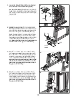
49. Wrap the Press Cable (72) under a 90mm Pulley

(35). Attach the Pulley and a Cable Trap (38) to
the indicated hole in the Press Upright (5) with an
M10 x 93mm Bolt (85), an M10 Washer (97) and
an M10 Nylon Locknut (90). Make sure the
Cable Trap is positioned to hold the Cable in
the groove of the Pulley.

49

38

5

35 

72 

85 

50. Route the Press Cable (72) through the opening

in the Press Frame (17) and wrap the Cable
around a 90mm Pulley (35) in the direction
shown. 

Attach the 90mm Pulley (35) and a Cable Trap
(38) to the indicated hole in the Press Frame (17)
with an M10 x 81mm Bolt (104), an M10 Washer
(97) and an M10 Nylon Locknut (90). Make sure
the Pulley is attached on the inside of the
Press Frame. Make sure the Cable Trap is
positioned to hold the Cable in the groove of
the Pulley.

50

104

97

35

90

38

17

51. Wrap the Press Cable (72) around a “V”-pulley

(34) in the direction shown. Attach the “V”-pulley
and a Long Cable Trap (37) to the small tube on
the Press Upright (5) with an M10 x 81mm Bolt
(104), an M10 Washer (97) and an M10 Nylon
Locknut (90). Note: The small tube has four
adjustment holes. The “V”-pulley must be
attached at the hole farthest from the Upright.
Make sure the Cable Trap is oriented as
shown. 

52. Wrap the Press Cable (72) around a 90mm

Pulley (35) in the direction shown. Attach the
Pulley and a Cable Trap (38) at the indicated hole
in the Press Frame (17) with an M10 x 81mm Bolt
(104), an M10 Washer (97), and an M10 Nylon
Locknut (90). Make sure the Pulley is attached
on the inside of the Press Frame. Make sure
the Cable Trap is positioned to hold the Cable
in the groove of the Pulley.

51

52

35

17

90

97

38

72

97

90

104

34

37

5

104

72

90

97

72

Содержание 831.159833

Страница 1: ...this manu al for future reference WEIGHT SYSTEM EXERCISER User s Manual Model No 831 159833 Serial No Write the serial number in the space above for reference Serial Number Decal under seat Sears Roeb...

Страница 2: ...ESHOOTING AND MAINTENANCE 28 CABLE DIAGRAMS 30 ORDERING REPLACEMENT PARTS Back Cover FULL 90 DAY WARRANTY Back Cover Note A PART LIST EXPLODED DRAWING and a PART IDENTIFICATION CHART are attached in t...

Страница 3: ...d cause the weight system to tip 11 Never release the press arm butterfly arms leg lever leg press plate lat bar ab strap or nylon strap while weights are raised the weights will fall with great force...

Страница 4: ...rdiovascular system the weight system will help you to achieve the results you want For your benefit read this manual carefully before using the weight system If you have questions after reading this...

Страница 5: ...several hours By setting aside plenty of time and by deciding to make the task enjoyable assembly will go smoothly Select a Location for the Weight System Because of its weight and size the weight sys...

Страница 6: ...rence between them is the dis tance between the holes When you need a support plate find the kind with holes that will fit over the bolts you are using Attach the Center Base 2 to the Butterfly Base 1...

Страница 7: ...p of the Butterfly Upright 4 with two M8 x 66mm Bolts 89 a Medium Support Plate 109 and two M8 Nylon Locknuts 86 Do not tighten the Locknuts yet 5 86 86 67 109 4 4 1 75 67 67 7 86 89 6 Press a 50mm Sq...

Страница 8: ...1 4 1 86 86 86 100 75 75 76 112 69 86 86 86 86 90 6 3 5 7 Slide the Butterfly Leg 11 onto the two M8 x 61mm Carriage Bolts 75 in the Butterfly Base 1 Hand tighten two M8 Nylon Locknuts 86 onto the Bol...

Страница 9: ...the Left Weight Guides Insert the Left Weight Guides into the indicated holes in the Center Base 2 Set the other two Weight Bumpers 46 over the indicated holes in the Center Base 2 Insert the Right W...

Страница 10: ...2 44 26 41 45 Pin Grooves Welded Pin 13 14 14 Slide the Bottom Weight 47 and seven Weights 41 onto the Left Weight Guides 27 Make sure the decal on the Bottom Weight is in the indi cated location and...

Страница 11: ...rear hole in Center Top Frame 8 to the Press Top Frame 9 with an M10 x 69mm Bolt 92 a Large Support Plate 29 and an M10 Nylon Locknut 90 Do not tighten the Locknut yet Locate the parts bag labeled PUL...

Страница 12: ...Arm 18 to the Press Frame 17 with two M8 x 62mm Bolts 87 and two M8 Nylon Locknuts 86 Repeat this step with the other Press Arm 18 21 68 18 18 17 86 87 66 Arm Assembly 18 Locate and open the parts bag...

Страница 13: ...ckets 55 54 68 53 19 68 20 23 Locate and open the parts bag labeled CABLE ASSEMBLY For cable identification and routing during steps 23 to 61 refer to the CABLE DIAGRAMS and CABLE ID CHART on pages 30...

Страница 14: ...t 31 with an M10 x 45mm Bolt 94 and an M10 Nylon Locknut 90 25 35 73 31 94 90 4 114 73 34 37 27 Attach the Butterfly Cable 73 to the bracket on the Right Butterfly Arm 19 with an M8 x 20mm Shoulder Bo...

Страница 15: ...le in the pair of Pulley Plates 32 with an M10 x 48mm Bolt 93 and an M10 Nylon Locknut 90 Make sure the Cable Trap is posi tioned to hold the Cable in the groove of the Pulley 29 15 30 Wrap the Rear C...

Страница 16: ...38 90 90 31 35 74 94 35 Wrap the Ab Cable 74 under a 90mm Pulley 35 Attach the Pulley and a Cable Trap 38 to the indicated bracket on the Butterfly Base 1 with an M10 x 48mm Bolt 93 and an M10 Nylon L...

Страница 17: ...ep 39 39 74 35 35 35 90 90 77 2 95 94 2 35 74 Bracket 38 39 Remove the M10 x 97mm Bolt 77 and the M10 Nylon Locknut 90 used in step 37 Wrap the Ab Cable 74 under a 90mm Pulley 35 as shown Attach the P...

Страница 18: ...ke sure the Cable Trap is positioned to hold the Cable in the groove of the Pulley 35 93 71 Cable Guide 1 90 43 Wrap the Low Cable 71 under a 90mm Pulley 35 Attach the Pulley and a Cable Trap 38 to th...

Страница 19: ...71 102 4 35 38 46 100 108 86 13 71 47 Identify the Press Cable 72 It is approximately 387 5 8 long and it has a ball on one end and a threaded shaft on the other Wrap the Press Cable 72 over a 90mm P...

Страница 20: ...sitioned to hold the Cable in the groove of the Pulley 50 104 97 35 90 38 17 51 Wrap the Press Cable 72 around a V pulley 34 in the direction shown Attach the V pulley and a Long Cable Trap 37 to the...

Страница 21: ...l be attached to the Bolt in step 56 Make sure the Cable Trap is posi tioned to hold the Cable in the groove of the Pulley 55 Wrap the Press Cable 72 around a V pulley 34 in the direction shown Attach...

Страница 22: ...ach the Pulley inside the indicated bracket on the Center Top Frame 8 with an M10 x 45mm Bolt 94 and an M10 Nylon Locknut 90 57 90 102 38 35 17 5 72 60 94 8 90 72 36 58 Wrap the Press Cable 72 around...

Страница 23: ...6 x 65mm Bolts 79 and two M6 Washers 99 63 Insert an M6 x 62mm Carriage Bolt 91 through the center hole in a Seat Plate 30 Using two M6 x 16mm Bolt 98 attach the Seat Plate to the Seat 23 with the ser...

Страница 24: ...tterfly Leg 11 Slide two Foam Pads 52 onto the ends of the Pad Tube 67 Attach the Curl Pad 22 to the Curl Post 21 with two M6 x 16mm Bolts 98 68 Make sure that all parts have been properly tightened T...

Страница 25: ...erformed The Nylon Strap 83 or Ab Strap 56 can be attached in the same manner The accessories can be attached to the ab pulley station or high pulley station in the same manner 59 40 56 58 58 57 15 Th...

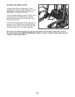
Страница 26: ...1 under the Bottom Weight Remove the other Weight Pin from the small weight stack To use the small weight stack with the press arms or leg press insert a Weight Pin 81 under the Bottom Weight 47 Then...

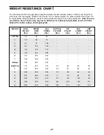
Страница 27: ...h station may vary due to differences in individual weight plates as well as friction between the cables pulleys and weight guides WEIGHT Left Top 1 2 3 4 5 6 7 Bottom Right Top 1 2 3 4 5 6 HIGH PULLE...

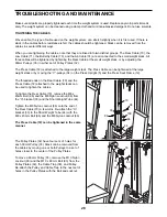
Страница 28: ...es in the Pulley Plates with the Bolt and Locknut TROUBLESHOOTING AND MAINTENANCE Make sure all parts are properly tightened each time the weight system is used Replace any worn parts immedi ately The...

Страница 29: ...and Locknut If there is still slack in the Press Cable 72 move the V pulley 34 attached to the small tube on the Press Upright 5 to a hole that is closer to the Upright Remove the M10 x 69mm Bolt 92...

Страница 30: ...he Ab Cable 74 The numbers show the correct route for each Cable Make sure that the Cables are routed correctly that the Pulleys move smoothly and that the Cable Traps do not touch or bind the Cables...

Страница 31: ...Low Cable 71 5 4 3 1 2 6 7 3 1 8 9 10 11 5 6 2 1 4 1 2 4 3 2 3 Butterfly Cable 73 5 Rear Cable 70 31 4 Ab Cable 74...

Страница 32: ...M8 x 66mm Bolt 89 M10 x 69mm Bolt 92 M10 x 48mm Bolt 93 M10 x 45mm Bolt 94 M8 x 45mm Bolt 96 M10 x 58mm Bolt 114 M8 x 20mm Shoulder Bolt 84 M8 Washer 100 M8 x 58mm Bolt 110 M8 x 62mm Bolt 87 M6 Washe...

Страница 33: ...Bolt 91 M10 x 91mm Bolt 101 M10 x 121mm Bolt 102 M10 x 72mm Bolt 105 M10 x 207mm Bolt 106 M10 x 92mm Carriage Bolt 112 M10 x 78mm Bolt 107 M10 x 100mm Bolt 115 M10 x 84mm Bolt 78 M10 x 89mm Carriage...

Страница 34: ...25mm Retainer 54 25mm Round Cover Cap 55 25mm Round Inner Cap 66 19mm Round Inner Cap 64 50mm Square Inner Cap 67 45mm Square Inner Cap 68 25mm Square Inner Cap 69...

Страница 35: ...Bar 60 2 Plastic Bushing 61 2 Large Bushing 62 4 Handgrip 63 4 M10 Large Washer 64 4 19mm Round Inner Cap 65 2 Butterfly Arm Bushing 66 2 25mm Round Inner Cap 67 15 50mm Square Inner Cap 68 7 45mm Sq...

Страница 36: ...86 86 90 80 90 90 88 86 90 90 90 97 86 86 97 115 90 89 89 79 93 86 86 90 97 90 86 90 103 86 86 79 90 113 113 86 90 77 92 89 102 97 90 93 90 94 90 90 94 90 90 90 90 90 97 97 105 86 96 90 90 86 79 97 7...

Страница 37: ...tact the nearest Sears Service Center throughout the United States and Sears will repair or replace the WEIGHT SYSTEM EXERCISER free of charge This warranty does not apply when the WEIGHT SYSTEM EXERC...

Отзывы: