background image

14 


1

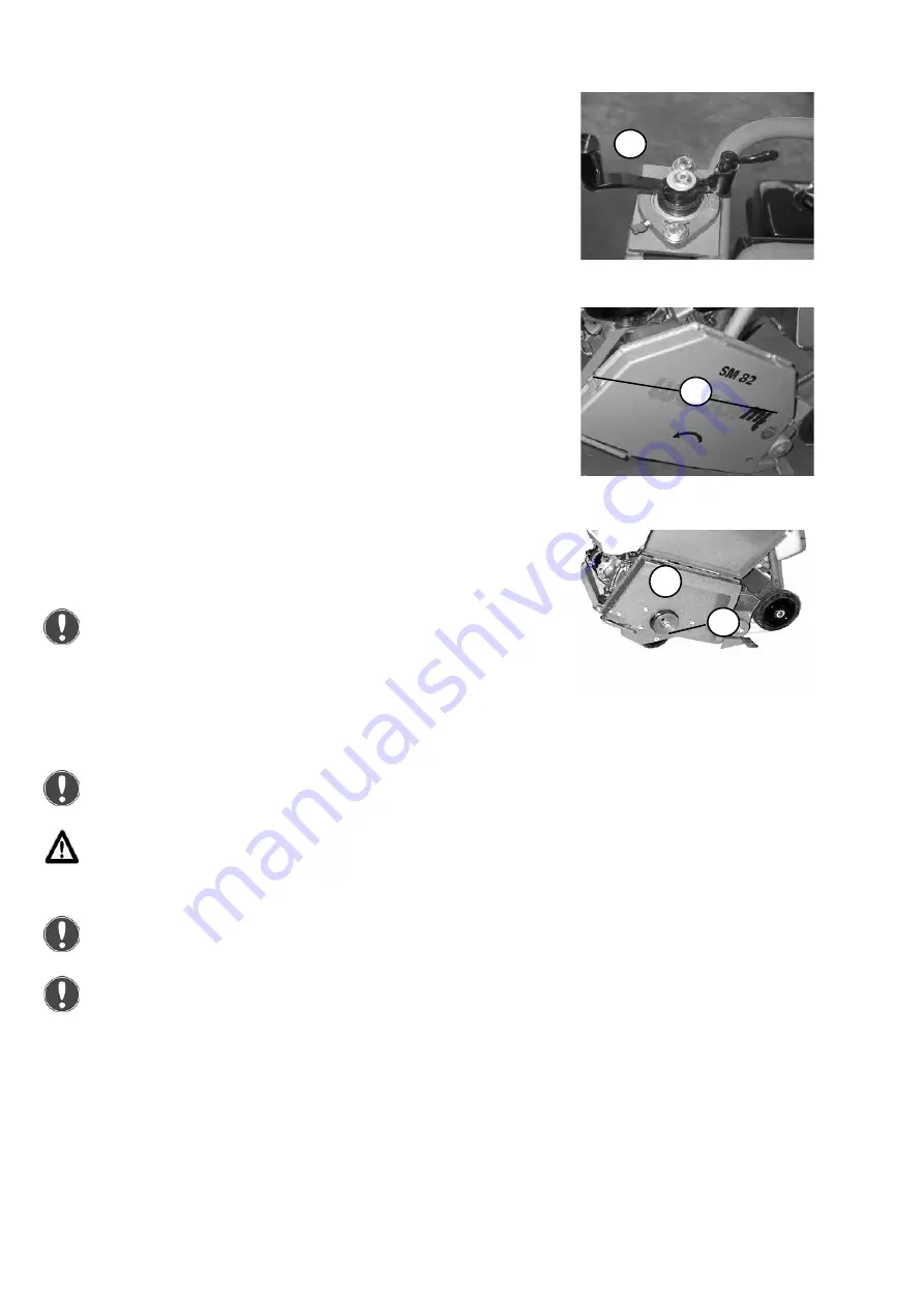
Install the cutting disk

Turn the cutting disk protection into the highest position with 

the crank (1).

Open the cutting disk protection by releasing both clamps (1).

Unscrew the securing screw (1).

Remove the flange cover (2) with the ring flange and sealing 

ring from the hub.

After removing the parts, clean them thoroughly and check 

them for damage.


2

1

Installing the cutting disk

Fit the cutting disk as follows:

Sealing ring, ring flange, cutting disk, flange cover. The 

flange cover must be fastened with the Allen screw.

The support surface of the clamping disk and the hub 

must be free of notches and any other damage. Otherwise 

the cutting disk might wobble.

The cutting disk must be flat on the hub. The grooved pin 

locks the cutting disk in its cutting direction.

When installing the cutting disk, the arrows of the cutting 

disk and the cutting disk protection must point in the 

same direction.

1

Содержание SM 82-3

Страница 1: ...1 Operating and Maintenance Manual SM 82 3 0401703...

Страница 2: ...2...

Страница 3: ...raphic presentation 8 Device description 9 Technical data 10 Activities prior to starting work 12 Starting 15 Cutting 16 Taking out of operation 17 Maintenance overview 18 Maintenance work 19 Operatin...

Страница 4: ...increase the reliability and service life of your joint cutter This operating and maintenance manual must always be available where the joint cutter is used If necessary you can obtain additional info...

Страница 5: ...owner shall be exclusively responsible All liability is rejected if damage occurs due to non compliance with this provision This risk is borne solely by the user Operation Joint cutters must only be o...

Страница 6: ...and livestock Hydraulic hose lines must be checked at regular intervals in accordance with standard engineering practice or they must be replaced at appropriate intervals even if no signs of safety r...

Страница 7: ...connections etc against water penetration by masking them off Cleaning tasks should only be executed in areas that are suitable and have been approved for this purpose oil separator amongst others Dis...

Страница 8: ...2 1 Hand guidance rod 2 Water tank 3 Fuel tank 4 Engine 5 Scale for cutting depth 6 Cutting disk protection 7 Cutting disk 8 Cutting depth adjustment wheel 9 Hearing protection sticker 10 Transport ha...

Страница 9: ...g disk up the back left wheel is clamped The cutting machine is now secure and will not roll away The supply of water from the water tank serves to bind with the dust during cutting with dry cutting d...

Страница 10: ...Operating speed 1 min 3600 Cutting disk Disk speed rotations per minute 1910 Cutting speed m s 50 Cutting depth mm 190 SM 82 3 Noise emissions in accordance with 2000 14 EC Sound pressure level LPA as...

Страница 11: ...11 1 Description 2 Type 3 Serial number 4 Year of manufacture 5 Weight 6 Rated power kW 2 1 3 4 5 6...

Страница 12: ...r neck with clean fuel in accordance with the specification The correct oil level is between the min and max marks Checking the engine oil level Pull the oil dipstick 1 out of the crankcase Check the...

Страница 13: ...lean water Close water tank securely with cap 2 Open the stop cock 1 for sprinkling the water Water supply over the water connection Remove the coupling of the water connector 1 from the water tank Co...

Страница 14: ...2 1 Installing the cutting disk Fit the cutting disk as follows Sealing ring ring flange cutting disk flange cover The flange cover must be fastened with the Allen screw The support surface of the cl...

Страница 15: ...oke lever 1 to the left close Open the fuel cock 2 After the engine has warmed up slide the choke lever to the right open Slowly tighten the handle 1 of the reversing starter 2 until resistance is not...

Страница 16: ...o bind with the dust Align the pointer 1 to the marked cut line Risk of getting cut on the rotating cutting disk Push the gas lever 1 all the way to the front towards the machine to the full throttle...

Страница 17: ...urn the short circuit button to the 0 OFF position Close the water cock 1 During breaks even if they are short the ma chine must be shut down Parked devices that represent an obstacle must be safeguar...

Страница 18: ...to contact with skin they can cause skin cancer Upon contact with the skin clean affected skin with suitable cleaning agent without delay If accessible during maintenance check the condition and stabi...

Страница 19: ...move the air filter insert 1 from the air filter enclosure Clean air filter insert as specified by the engine manufacturer if there is damage or if it is extremely dirty Maintenance work Onlydrainengi...

Страница 20: ...ck nut 2 from the locking screw 1 Tighten clamping screw turn to right until the desired V belt tension is reached Tighten all four screws 3 of the engine fixing Secure the clamping screw 1 with lock...

Страница 21: ...2 Lubricate with pressure grease gun until fresh grease emerges Close lubrication nipple 1 with protective cap Lubricating the elevation screw Remove sight cap 1 from the elevation screw guard 2 Greas...

Страница 22: ...k Petrol Unleaded petrol 6 5 l Water tank Clean water 35 0 l Lubricating points High pressure grease saponified with lithium As necessary in accordance with IDN 51825 KPF2 Fault Possible cause Remedy...

Страница 23: ...el up to the lower edge of filler neck Engine Check oil level if necessary fill to upper oil level mark Check air filter clean replace if necessary Check fuel filter change if necessary All bare parts...

Страница 24: ...24...

Страница 25: ...25...

Страница 26: ...26...

Страница 27: ...27...

Страница 28: ...MT youtube com MyWeberMT 085106101 104 SM 82 3_2020_05_EN Original instructions Weber Maschinentechnik GmbH Im Boden 5 8 10 57334 Bad Laasphe Germany Phone 49 2754 398 0 Fax 49 2754 398 101 info weber...

Отзывы: