WDT Operating instructions GRANUDOS 10 (V61-08/05) page 5 of 20
____________________________________________________________________________
1.3 Dissolving System
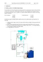
The dissolving water is normally supplied from before or from behind the filter. There must be a
sufficient supply pressure to avoid dry running and/or cavitation on the booster pump, at least
0.2 bar. The pump pressure is controlled by the pressure switch (20) fitted on top of the pump. At a
pressure below the set switch pressure by sucking air or at pressure drops the machine stopps, lamp 1 &
2 will burn. At works 1,5 bar is set.
The supply water is divided at the discharge of the booster pump (26), one way leading to the flushing
tank (22), the other branch directed to the venturi nozzle (25), where the water is sucked together with
the dosed chemicals out of the flushing tank. The supply water flow is controlled by means of a floating
valve (21) and a flow switch (24), the latter being installed in the suction tube of the venturi. To mix the
chemicals and to ensure the complete dissolving of the chlorine granules a cyclone mixing chamber
(27) is fitted after the venturi.. To ensure that
chlorine
and acid do not come into contact with each
other in the open tank part of the dissolving assembly a sophisticated control system is installed:
-
metering of the two chemicals is regulated with pauses between the metering intervals (para 3.7
“Adjusting dosing performance”).
-
power supply for chlorine and acid dosing motors are connected by a relay system so that only one
or none of them can get power (24VDC) and dose chemical.
-
flow switch (24) , level switch (29), pressure switch (20) supervising water supply and flow
conditions. If any non-compliance with the given limits occurs, the GRANUDOS will be switched
off.
If any non-compliance with the given limits occurs, the chemical dosing will be stopped.
7
pressure switch
13
venturi nozzle
8
floating valve
14
orifice washer
9
booster pump Lo 2HMS3
15
level switch low/high
10 flow switch holder with flow switch
16
lid on flushing tank
11 acid dosing valve
with chlorine dust protection
12 mixing and dissolving
17
overflow to drain
chamber with PVC ball valve
The flushing tank is an open system with two ways for a drain of water coming from the circulation to
the flushing tank and possibly causing an overflow at switch off times. To avoid this, the flow switch
holder as the floating valve are acting as non return valves: The floating valve closes the inlet bore at
rising level (proved up to 4 bars at test), in addition a spring loaded non return valve is installed in the
elbow fitting into the valve. The switch bobbin has a seal to close this way. Both devices function well
if the seal/diaphragm are maintained in a good shape. But as a mechanical seal may leak after any time
or by being blocked by impurities a 100% isolation may not be guaranteed. If this is needed for any
cases, an electric valve must be installed.
7
8
9
10
11
12
14
13
15
16
17


