background image

107

November 1992

Part No. 917543  Rev. A

B.4.3.

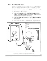
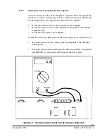
Power Output to the Displays

The data output from the computer to the displays cannot be readily field tested.
The +4.8 to 5.2 VDC supplied to the displays from the computer, on the other
hand, can be tested.  To test the 5 volts to the displays perform the following steps:

Set your meter on the 20 VDC scale.

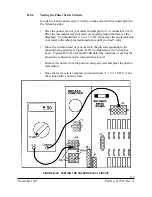
Connect the common lead of your meter to pin 2 of either the J4 or J5
connector (depending on whether the side 1 or side 2 display circuitry is
being tested) on the computer (see Figure B-13).

Connect the positive lead of your meter to pin 1 of the J4 or J5 connector
on the computer.

Your meter should read +4.8 to 5.2 VDC if not the computer is defective.

FIGURE B-13.  TESTING THE OUTPUT TO THE DISPLAYS

Содержание Vista Series

Страница 1: ...SERVICE Vista Blending and Non blending Suction Pumps and Remote Dispensers...

Страница 2: ...circuits in the dispenser are de energized CAUTION To prevent damage to moving parts located in the hydraulic cabinet dispenser doors should be in place during rainy and or icy weather conditions If...

Страница 3: ...November 1992 Part No 917543 Rev A Vista Blending Dispensers and Non blending Suction Pumps and Remote Dispensers Service Manual...

Страница 4: ...Part No 917543 Rev A November 1992...

Страница 5: ...rinsic Safe Barrier Printed Circuit Board 15 3 6 Pulser Assembly 15 3 6 1 Photocoupler 15 3 6 2 Pulser Disc 18 3 7 Suction Pump Motor 18 3 8 Blend Motor 18 4 MECHANICAL PARTS 21 4 1 Nozzle Boot with M...

Страница 6: ...2 Fault Code 06 52 Fault Code 08 53 Fault Code 10 53 Fault Code 11 53 Fault Code 12 53 Fault Code 13 53 Fault Code 14 15 16 53 Fault Code 20 52 Fault Code 21 53 Fault Code 51 54 7 COMPONENT REPLACEMEN...

Страница 7: ...ING Back Cover LIST OF FIGURES Figure 1 1 Proportional Blending Block Diagram 2 Figure 1 2 Fixed Ratio Blending Block Diagram 4 Figure 2 1 Bezel and Function Switch Location 6 Figure 2 2 Unit Price Di...

Страница 8: ...Figure 7 1 Replacing the Duplex II Computer 57 Figure 7 2 Replacing the Intrinsic Safe Barrier Board 59 Figure 7 3 Replacing the Integrated Display Board 60 Figure 7 4 Replacing the Lighted Cash Credi...

Страница 9: ...ispenser Electronic Module DEM 97 B 4 Testing the Duplex II Computer 99 B 4 1 The AC Input to the Solenoid Drive Board 105 B 4 2 Output to the Pulsers and Handle Switches 106 B 4 3 Power Output to the...

Страница 10: ...rd 112 Figure B 18B 4 Product Solenoid Drive Board 113 Figure B 18C Blender Solenoid Drive Board 114 Figure B 19 Solenoid Drive Board Connector J1 and J2 Pin Definitions 115 Figure B 20A 4 product Sol...

Страница 11: ...D 138 3 6560 D Internal Wiring Diagram V399D 139 5 6560 D Internal Wiring Diagram V490D 140 7 6560 D Internal Wiring Diagram V590D 141 9 6560 D Internal Wiring Diagram V387D 142 11 6560 D Internal Wir...

Страница 12: ...x Part No 917543 Rev A November 1992...

Страница 13: ...or to the appropriate regional service manager Wayne Technical Services 1 800 926 3737 Austin TX 24 hours 7 days Eastern Regional 410 546 6750 Service Office 8 30AM 5 00 PM E S T Salisbury MD Southea...

Страница 14: ...d Valve and Blend Motor Pulsers HI Product Meter Lo Product Meter LO Product Inlet HI Product Inlet Electrical Connections Mechanical Drive Hydraulic Tubing LINE STYLE DEFINITIONS Blend Product Nozzle...

Страница 15: ...input to separate chambers in the blend valve the blend valve is designed in such a way that the outputs from these chambers can be controlled By manipulating the valve the flow from one chamber can b...

Страница 16: ...lend Valve Pulsers HI Product Meter Lo Product Meter HI Product Diaphragm Valves LO Product Diaphragm Valves LO Product Inlet HI Product Inlet Electrical Connections Mechanical Drive Hydraulic Tubing...

Страница 17: ...he slow valve coil is energized two to six seconds depending on option program ming settings after the submersible pump relay is energized After a small amount of fuel has been dispensed the fast valv...

Страница 18: ...play Wing Head Thumbscrew or Bezel Lock Authorize Switch Totals Pushbutton Position Select Pushbutton Price Jog Pushbutton DCPT Power Optional Attend Self Serve ON OFF Typical Vista Bezel With Ad Pane...

Страница 19: ...closure of the Position Select pushbutton selects position X unit price credit price of Cash Credit type dispenser and will blank the Unit Price displays for the position Y Z and AA The unit price fo...

Страница 20: ...ash unit price MID blend position Seventh Closure Credit unit price HI MID blend position Eighth Closure Cash unit price HI MID blend position NinthClosure Credit unit price HI feedstock or highest ra...

Страница 21: ...econd Closure Unit price position Y Cash unit price position X Third Closure Unit price position Z Credit unit price position Y Fourth Closure Unit price position AA Cash unit price position Y 490 Ser...

Страница 22: ...ser represents two fueling points The fueling point number is set as follows The Position Select pushbutton is used to enter the fueling point setting mode The Totals pushbutton sets the fueling point...

Страница 23: ...e decoding circuits and the drivers for the LCD s are located on the display board 3 2 LIGHTED CASH CREDIT INTERFACE BOARD The lighted cash credit interface board performs two functions First is the s...

Страница 24: ...e controls all AC voltage supplied to the solenoid drive board If the F1 fuse opens the dispenser will reset but no valves or relays will be energized 3 4 COMPUTER ASSEMBLY see Figure 3 1 The computer...

Страница 25: ...Connection Side 1 J8 Blend Motor Connection Side 2 CONNECTOR DESCRIPTIONS COMPUTER J1 Data Loop Both Sides J3 AC Input J4 Displays Side 1 J5 Displays Side 2 J6 Future Diagnostic Use J9 Pulser Control...

Страница 26: ...ng the two pins which are closest to the edge of the board for blending applications In addition to the jumper settings there are programming options which must be set in order for the Duplex II Compu...

Страница 27: ...begin a new sale if the dispenser has been authorized and the push to start or cash credit select switch has been pressed The Intrinsic Safe Barrier Printed Circuit Board contains current limiting re...

Страница 28: ...isable NNN Sequence Number in the range of 000 999 CC Fault Code number in the range of 00 99 F Fault Source This value identifies the fault source if the fault can be linked to a particular hydraulic...

Страница 29: ...erisk next to a number in the Status column indicates the default status for that Fault Code More than one number in the status column indi cates that the status of that Fault Code is alterable The fa...

Страница 30: ...operated on either 110 VAC or 220 VAC depending on a switch setting The voltage selection switch is located on the side of the motor and is secured by a sheet metal screw To change the operation of th...

Страница 31: ...19 November 1992 Part No 917543 Rev A FIGURE 3 3 NON BLENDING PHOTOCOUPLER INTERNAL WIRING Photocoupler Pulser Disc PULSER SELECT 0 VDC PUL A LED B LED A PUL B JDB FH 115 A...

Страница 32: ...OTOCOUPLER INTERNAL WIRING Blend Pulser Select V BK Pul B LO V R Pul B HI BU BK LED A 5 VDC OR LED B 5 VDC OR BK PUL A HI BU PUL A LO Y WIRE COLORS V Violet Y Yellow BU Blue BK Black OR Orange R Red J...

Страница 33: ...e a VOM you should read continuity Slowly push the flipper toward the OFF position The switch contacts should open when the flipper has traveled approximately 1 2 inch Place the nozzle in the nozzle b...

Страница 34: ...22 Part No 917543 Rev A November 1992 FIGURE 4 1 NOZZLE BOOT ASSEMBLY WITH MICRO SWITCH...

Страница 35: ...23 November 1992 Part No 917543 Rev A FIGURE 4 2 NOZZLE BOOT ASSEMBLY WITH TILT SWITCH...

Страница 36: ...24 Part No 917543 Rev A November 1992...

Страница 37: ...ary to clean the strainer screen two or three times the first few days of operation to remove debris and pipe dope After this occasional cleaning of the strainer is all that should be required The fue...

Страница 38: ...the diaphragm into and out of full flow The actuator coils control the actuator itself When the coils are energized poppets inside the actuator are moved to expose flow paths through the actuator Tog...

Страница 39: ...nlet chamber to outer chamber 3 Orifice through valve plate to center chamber 4 Passageway to the actuator inlet from the center chamber 5 Actuator outlet 6 Relief valve 7 Center section 8 Diaphragm m...

Страница 40: ...ctuator 2 Passageway from inlet chamber to outer chamber 3 Orifice through valve plate to center chamber 4 Passageway to the actuator inlet from the center chamber 5 Actuator outlet 6 Relief valve 7 C...

Страница 41: ...TER CHAMBER REMOVED OUTLET PORT A A A INLET OUTLET 2 4 Indicates Part of Casting JDB FH 126 B 2 Passageway from inlet chamber to outer chamber 4 Passageway to the actuator inlet from the center chambe...

Страница 42: ...er are equal at this point Because the area of the diaphragm material 8 exposed to the inlet chamber is approximately half that exposed to the center chamber the force holding the diaphragm closed is...

Страница 43: ...inlet chamber to outer chamber 3 Orifice through valve plate to center chamber 4 Passageway to the actuator inlet from the center chamber 5 Actuator outlet 6 Relief valve 7 Center section 8 Diaphragm...

Страница 44: ...ctuator 2 Passageway from inlet chamber to outer chamber 3 Orifice through valve plate to center chamber 4 Passageway to the actuator inlet from the center chamber 5 Actuator outlet 6 Relief valve 7 C...

Страница 45: ...rds the center chamber This opens a path directly from the inlet to the outlet initiating full flow When the delivery is complete both actuator coils are de energized allowing the poppets to return to...

Страница 46: ...inlet chamber to outer chamber 3 Orifice through valve plate to center chamber 4 Passageway to the actuator inlet from the center chamber 5 Actuator outlet 6 Relief valve 7 Center section 8 Diaphragm...

Страница 47: ...ctuator 2 Passageway from inlet chamber to outer chamber 3 Orifice through valve plate to center chamber 4 Passageway to the actuator inlet from the center chamber 5 Actuator outlet 6 Relief valve 7 C...

Страница 48: ...rom inlet chamber to outer chamber 3 Orifice through valve plate to center chamber 4 Passageway to the actuator inlet from the center chamber 5 Actuator outlet 6 Relief valve 7 Center section 8 Diaphr...

Страница 49: ...B 1 Actuator 2 Passageway from inlet chamber to outer chamber 3 Orifice through valve plate to center chamber 4 Passageway to the actuator inlet from the center chamber 5 Actuator outlet 6 Relief valv...

Страница 50: ...ut shaft By connecting the output shaft to the pulser assembly the rotary movement of the meter can be converted into pulses which can in turn be counted by the computer Calibration is made possible b...

Страница 51: ...e to center chamber 4 Passageway to the actuator inlet from the center chamber 5 Actuator outlet 6 Relief valve 7 Center section 8 Diaphragm material 9 Valve plate 10 Cover 11 Body 12 Slow flow poppet...

Страница 52: ...B 1 Actuator 2 Passageway from inlet chamber to outer chamber 3 Orifice through valve plate to center chamber 4 Passageway to the actuator inlet from the center chamber 5 Actuator outlet 6 Relief val...

Страница 53: ...41 November 1992 Part No 917543 Rev A FIGURE 5 7 METER CUTAWAY...

Страница 54: ...42 Part No 917543 Rev A November 1992 FIGURE 5 8 METER ADJUSTMENT...

Страница 55: ...ing systems The bypass valve in the compact pumping unit should be set at one of two pressures If the pumping unit is driven by a 1 3 horsepower motor the pressure should be 21 22 psi If the motor is...

Страница 56: ...mber 1992 FIGURE 5 9 BLEND VALVE Low Product Chamber High Product Chamber Adjusting Lever High Product Outlet High Product Shoe Low Product Outlet Low Product Shoe High Product Inlet Low Product Inlet...

Страница 57: ...top of the sump assembly is an orifice connected to the nozzle boot via a copper tube This tube provides an outlet for the vapors Along with this vapor is a small amount of product This fluid remains...

Страница 58: ...46 Part No 917543 Rev A November 1992...

Страница 59: ...inted circuit board Remove the short from the J6 connector Enter option 97 the money display will show XXXAB XXXAB represents a number up to 5 digits Enter AB as BA For instance if 91 is shown in the...

Страница 60: ...Check for 5VDC off zero will not respond to volts on replace switch if voltage individual function switch is constant at either 5 or 0 i e the totals switch or the price jog switch 2 Defective wiring...

Страница 61: ...4 Fueling point not set Set fueling point If a control system is not connected skip to step 5 5 Defective computer Replace Computer will not reset 1 Unit prices 0 00 See above 2 No authorize to Refer...

Страница 62: ...ctuator coil Check coils for continuity if open circuit replace defective coil 4 Defective stuck Check both valves Replace or actuator or diaphragm rebuild as necessary 5 Defective computer Replace as...

Страница 63: ...the DEM where the push to start switch normally is connected Repair or replace the wiring as necessary 2 Defective lighted cash Replace the cash credit interface credit interface board board 3 Defecti...

Страница 64: ...ft must be aligned in between pulser drive center of coupling gear on meter shaft and coupling To align loosen mounting bolts gear on meter on pulser housing and reposition housing 6 Defective photoco...

Страница 65: ...pted and reset to zero 1 If error reoccurs Replace computer defective computer Fault code 13 Unit price data was found corrupted and reset to zero 1 If error reoccurs Replace computer defective comput...

Страница 66: ...Replace the solenoid drive board drive board 5 Defective F2 on Replace F2 computer 6 Defective computer Replace computer 7 Defective blend Replace blend motor motor To check for a defective Blend Mot...

Страница 67: ...age to electronic components due to static electricity Always keep replacement components in their anti static shipping bags until they are installed Put replaced suspect components in the anti static...

Страница 68: ...s functional 2 Turn OFF the control power 3 Put the appropriate switch in the data distribution box to bypass 4 The computer is located behind and below the consolidated display on the junction box si...

Страница 69: ...57 November 1992 Part No 917543 Rev A FIGURE 7 1 REPLACING THE DUPLEX II COMPUTER...

Страница 70: ...onics enclosure under a black metal cover 1 Remove the bezel opposite the junction box side 2 Remove black metal protective shroud 3 Remove connectors 4 Remove mounting screws from PCB assembly 5 Repl...

Страница 71: ...59 November 1992 Part No 917543 Rev A FIGURE 7 2 REPLACING THE INTRINSIC SAFE BARRIER BOARD...

Страница 72: ...60 Part No 917543 Rev A November 1992 FIGURE 7 3 REPLACING THE INTEGRATED DISPLAY BOARD...

Страница 73: ...ition and reinstall the bezel 7 1 6 Solenoid Drive Board Replacement see Figure 7 5 Note Even though the dispenser control power is turned off voltage may still be present at the solenoid drive board...

Страница 74: ...62 Part No 917543 Rev A November 1992 FIGURE 7 4 REPLACING THE LIGHTED CASH CREDIT INTERFACE BOARD...

Страница 75: ...63 November 1992 Part No 917543 Rev A FIGURE 7 5 REPLACING THE SOLENOID DRIVE BOARD...

Страница 76: ...the pulser disc down until it contacts the step and tighten the screws the disc will automatically be centered 5 Reconnect the cable to the photocoupler 6 Rotate the disk through two or three revoluti...

Страница 77: ...he flipper is released If the dispenser fails to reset use a VOM or ohmmeter to check for continuity across the switch assembly leadwires at the 2 pin connector 7 1 9 Actuator Module Replacement Modul...

Страница 78: ...the printed circuit board and switches 4 Install the new printed circuit board and switches using the previously removed screws 4 Reconnect all wiring harnesses and test for proper operation 7 1 11 Li...

Страница 79: ...e valve body Care must be taken during assembly to be sure the plate has not slipped and become pinched between the diaphragm and the body Be sure to install the red tinted back up plate in diaphragm...

Страница 80: ...screws which secure the actuator to the diaphragm cast ing and remove the actuator 5 Install the actuator onto the new diaphragm casting and reinstall the diaphragm using the reverse procedure Be sur...

Страница 81: ...t valve and shut off the sub mersible pump for the products in question On some dispenser models one of the blend valves will be located inside the side column of the dispenser Verify the location of...

Страница 82: ...70 Part No 917543 Rev A November 1992...

Страница 83: ...des generated by the duplex computer it is necessary to correct the problem and cycle the control power to the computer or enter a 3 in option 99 in order to clear the message Even if the problem is c...

Страница 84: ...72 Part No 917543 Rev A November 1992...

Страница 85: ...h shorted Defective switch Check with VOM for continuity when switch is on Does the switch check good Check the wiring to the switch Repair or replace the defective wiring END Replace the defective sw...

Страница 86: ...bled but switch detected Ensure that the two wires normally connected to the PTS switch are shorted Replace the wiring which would attach to the PTS switch Is the problem corrected Replace the lighted...

Страница 87: ...olenoid drive board holding valve s open Is 110VAC present when it should not be Check diaphragm for leaks or debris holding it open Replace or clean as necessary Replace the two stage actuator Is the...

Страница 88: ...No 917543 Rev A November 1992 04 fault code ROM error Does the error reoccur Replace computer END NO YES SGM FH 103 Computer found defective ROM chip during self test Clear erroo FLOWCHART A 4 04 FAU...

Страница 89: ...oid drive board Is the wiring OK Replace photocoupler Is the problem corrected Replace the solenoid drive board Is the problem corrected Replace the computer END Clean dust from photocoupler If proble...

Страница 90: ...lve or relay on when it should not be Check the solenoid drive board for 110VAC output to a valve or relay Is 110VAC present Replace solenoid drive board Replace computer Is the problem corrected Repl...

Страница 91: ...e Time out limit exceeded See Option 12 in the Duplex II programming manual Operational error no corrective action END SGM FH 104 Dispenser was turned on but no product was despensed for more than the...

Страница 92: ...ES Error occurs while dispensing blend at proportional blender While dispensing feedstock at proportional blender Ensure that both submersible pumps are operating at equal bypass pressures Correct as...

Страница 93: ...9 11 FAULT CODE 11 fault code Corrupted option programming Does the error reoccur Replace computer END NO YES SGM FH 105 Computer found scrambled data in option programming Check all option programmin...

Страница 94: ...lt code Corrupted totals data Does the error reoccur Replace computer END YES SGM FH 106 Computer found the totals data to be corrupted and reset the data to zero Check that sales are now being totale...

Страница 95: ...v A 13 fault code Corrupted unit price data Does the error reoccur Replace computer END YES SGM FH 107 Computer found the unit price data to be corrupted and reset the data to zero Re enter unit price...

Страница 96: ...r 110VAC output to valves when there should be none Is there 110VAC present Replace the two stage actuator Is the problem corrected Replace the computer END Replace the solenoid drive board NO YES NO...

Страница 97: ...rs cracked shoes Repair replace as necessary Replace the solenoid drive board Is the problem corrected Replace the computer END Check the linkage to the blend valve for binding Correct as necessary Co...

Страница 98: ...tween pins 1 and 2 on the J5 connector Replace the display Replace the computer Is 110VAC present in junction box terminal 1 Correct station wiring Make sure control power circuit breaker is ON and po...

Страница 99: ...7543 Rev A Display s scrambled or missing segments Replace display board Is the problem corrected Replace data cable Is the problem corrected Replace the computer END YES YES NO NO JDB FH 216 A FLOWCH...

Страница 100: ...tch i e the totals switch works but the price jog does not Defective switch Check with VOM for continuity when switch is on Does the switch check good Check the wiring to the switch Repair or replace...

Страница 101: ...ng to switches check all wires repair or replace as needed Defective cash credit interface board Replace as necessary Is the problem corrected Replace the computer END Replace the switches YES NO YES...

Страница 102: ...tch Replace if defective Is the dispenser authorized Is the dispenser communicating Check fueling point at dispenser Reset if necessary Is the problem corrected Authorize dispenser from the control sy...

Страница 103: ...d valve s Is 110VAC present Check actuator or relay coil for continuity Is the coil reading an open circuit Check for 110VAC on valve and relay select wires in the junction box Is 110VAC present Repla...

Страница 104: ...Is this the only fueling point with 0 000 for unit prices Check the fueling point in this dispenser Reset if necessary Is the problem corrected Replace the computer s Ensure that the dispensers in que...

Страница 105: ...93 November 1992 Part No 917543 Rev A APPENDIX B ELECTRONIC ELECTRICAL COMPONENT TROUBLESHOOTING...

Страница 106: ...94 Part No 917543 Rev A November 1992...

Страница 107: ...ted in the dispenser junction box Total Gallons REGULAR PLUS SUPER Nozzle Boot Ad Panel Push to Start Bar Unit Price Display Main Sale Display Bezel FIGURE B 1 TYPICAL VISTA DISPENSER B 2 REMOVING THE...

Страница 108: ...style Vista bezels without phillips head screws shown below the ad panel is lowered by simply pulling the ad panel out and down from the top of the ad panel holder See also Figure 2 1 in Section 2 FI...

Страница 109: ...on perform the steps shown in Figure B 3 and B 4 Once the DEM is tilted into the service position you will have access to all of the elec tronic components in the dispenser It may or may not be necess...

Страница 110: ...98 Part No 917543 Rev A November 1992 FIGURE B 4 THE DEM IN THE SERVICE POSITION...

Страница 111: ...d Output to the pulsers and handle switches Power output to the displays Output to the annunciators Power output to the preset control board In addition to these four functions the input power to the...

Страница 112: ...100 Part No 917543 Rev A November 1992 FIGURE B 6 DUPLEX II COMPUTERS J3 CONNECTOR PINOUT...

Страница 113: ...101 November 1992 Part No 917543 Rev A FIGURE B 7 DUPLEX II COMPUTERS J9 AND J10 CONNECTOR PINOUT...

Страница 114: ...102 Part No 917543 Rev A November 1992 FIGURE B 8 DUPLEX II COMPUTERS J11 CONNECTOR PINOUT...

Страница 115: ...103 November 1992 Part No 917543 Rev A FIGURE B 9 DUPLEX II COMPUTERS J6 CONNECTOR PINOUT...

Страница 116: ...104 Part No 917543 Rev A November 1992 FIGURE B 10 DUPLEX II COMUTERS J1 CONNECTOR PINOUT...

Страница 117: ...your meter on AC at a voltage corresponding to the control power of the dispenser Place the common lead of your meter on pin 1 of the Duplex II s J8 con nector see Figure B 11 Place the positive lead...

Страница 118: ...s output perform the following steps Set your meter on the 20 VDC scale Place the common lead of your meter in pin 2 of either the J9 or J10 connector place the positive lead in the pin controlling th...

Страница 119: ...the displays perform the following steps Set your meter on the 20 VDC scale Connect the common lead of your meter to pin 2 of either the J4 or J5 connector depending on whether the side 1 or side 2 di...

Страница 120: ...following steps Set your meter on the 20 VDC scale Place the common lead of your meter on pin 2 of either the J13 or J14 connec tor depending on the side of the dispenser which is being serviced Place...

Страница 121: ...lay In order to test this output perform the following steps Set your meter on the 20 VDC scale Insert the common lead of your meter into pin 6 of the Duplex II comput ers J6 connector see Figure B 15...

Страница 122: ...tage which corresponds to the control power of the dispenser Push the common lead of your meter into pin 2 of the Duplex II computer s J3 connector see Figure B 16 Push the positive lead of your meter...

Страница 123: ...input to the 5 VDC regulator on the computer F2 fuses the input to the 12 VDC regulator and is present on blending computers only F3 fuses the AC input to the computer To test one of the pico fuses p...

Страница 124: ...ion the solenoid drive board switches the correct pulser ON at the proper time Note The following figures are shown for connector information only Figures B 18A B 18B and B 18C identifies each of the...

Страница 125: ...113 November 1992 Part No 917543 Rev A FIGURE B 18B 4 PRODUCT SOLENOID DRIVE BOARD...

Страница 126: ...114 Part No 917543 Rev A November 1992 FIGURE B 18C BLENDER SOLENOID DRIVE BOARD...

Страница 127: ...115 November 1992 Part No 917543 Rev A FIGURE B 19 SOLENOID DRIVE BOARD CONNECTOR J1 AND J2 PIN DEFINITIONS...

Страница 128: ...116 Part No 917543 Rev A November 1992 FIGURE B 20A 4 PRODUCT SOLENOID DRIVE BOARD J3 AND J4 CONNECTOR PIN DEFINITIONS...

Страница 129: ...117 November 1992 Part No 917543 Rev A FIGURE B 20B BLENDER SOLENOID DRIVE BOARD J7 AND J8 CONNECTOR PIN DEFINITIONS...

Страница 130: ...f your meter into the pin representing the function to be tested do not disconnect the wiring harness from the solenoid drive board Set your meter on AC at a voltage corresponding to the control power...

Страница 131: ...ove the positive lead of your meter to the other pins mentioned above until you read 5 volts Move the common lead of your meter to the pin corresponding to the function being tested see Figure B 22 do...

Страница 132: ...ons of the connectors on the solenoid drive board Place the positive lead of your meter in pin 3 of either the J9 or J10 connector depending on the side of the dispenser being serviced Manually rotate...

Страница 133: ...121 November 1992 Part No 917543 Rev A FIGURE B 24 MANUALLY TURNING THE PHOTOCOUPLER...

Страница 134: ...the wiring with the handle switches it uses zener diodes in order to eliminate the possibility of introducing over 5 VDC into the hydraulics cabinet Figures B 25 through B 27 show the connectors on th...

Страница 135: ...123 November 1992 Part No 917543 Rev A FIGURE B 26 INTRINSIC SAFE BARRIER J2 AND J5 CONNECTOR PINOUTS...

Страница 136: ...124 Part No 917543 Rev A November 1992 FIGURE B 27 INTRINSIC SAFE BARRIER J3 AND J6 CONNECTOR PINOUT...

Страница 137: ...barrier in the head of the dispenser Set your meter on DC voltage on the 20 volt scale Push your common meter lead into any of the pins which are identified as common see Figures B 25 through B 27 an...

Страница 138: ...switches to be inoperable In addition because the lighted cash credit interface board is connected in the display circuitry any problems with it can cause problems with the consolidated display scramb...

Страница 139: ...127 November 1992 Part No 917543 Rev A FIGURE B 29 LIGHTED CASH CREDIT INTERFACE BOARD...

Страница 140: ...128 Part No 917543 Rev A November 1992 FIGURE B 30 LIGHTED CASH CREDIT INTERFACE BOARD J3 CONNECTOR...

Страница 141: ...129 November 1992 Part No 917543 Rev A FIGURE B 31 LIGHTED CASH CREDIT INTERFACE BOARD J4 CONNECTOR...

Страница 142: ...130 Part No 917543 Rev A November 1992 FIGURE B 32 LIGHTED CASH CREDIT INTERFACE BOARD J6 CONNECTOR...

Страница 143: ...resistance as shown in Figure B 33 below The blend motor consist of two coils each having a resis tance of 130 ohms To measure the coil resistance disconnect the blend motor connector plug and use an...

Страница 144: ...132 Part No 917543 Rev A November 1992...

Страница 145: ...133 November 1992 Part No 917543 Rev A APPENDIX C DISPENSER INTERNAL WIRING DIAGRAMS...

Страница 146: ...134 Part No 917543 Rev A November 1992...

Страница 147: ...Nozzle Switch Nozzle AA Pin 6 Nozzle Common Pin 1 Relay Select Nozzle X Pin 2 Fast Valve Nozzle X Pin 3 Slow Valve Nozzle X Pin 4 Relay Select Nozzle Y Pin 6 Fast Valve Nozzle Y Pin 7 Pulser Select N...

Страница 148: ...4 Relay Select High Product Pin 6 Fast Valve High Product Pin 9 Slow Valve High Product Pin 12 Fast Valve Blended Product Pin 15 Slow Valve Blended Product Pin 7 Pulser Select J11 SOLENOID DRIVE BOAR...

Страница 149: ...24 A Pin 1 Single Product Handle Switch Pin 8 Blend Handle Switch Pin 3 Pulse B High Product Pin 6 Pulse A High Product Pin 5 Pulse B Low Product Pin 9 Pulse A Low Product Pin 7 LED A Pin 4 LED B J9 S...

Страница 150: ...138 Part No 917543 Rev A November 1992 1 6560 D INTERNAL WIRING DIAGRAM V390D...

Страница 151: ...139 November 1992 Part No 917543 Rev A 3 6560 D INTERNAL WIRING DIAGRAM V399D...

Страница 152: ...140 Part No 917543 Rev A November 1992 5 6560 D INTERNAL WIRING DIAGRAM V490D...

Страница 153: ...141 November 1992 Part No 917543 Rev A 7 6560 D INTERNAL WIRING DIAGRAM V590D...

Страница 154: ...142 Part No 917543 Rev A November 1992 9 6560 D INTERNAL WIRING DIAGRAM V387D...

Страница 155: ...143 November 1992 Part No 917543 Rev A 11 6560 D INTERNAL WIRING DIAGRAM V390P...

Страница 156: ...144 Part No 917543 Rev A November 1992 12 6560 D INTERNAL WIRING DIAGRAM V585D...

Страница 157: ...145 November 1992 Part No 917543 Rev A 13 6560 D INTERNAL WIRING DIAGRAM V395D...

Страница 158: ...146 Part No 917543 Rev A November 1992 19 6560 D INTERNAL WIRING DIAGRAM V390D J SINGLE HOSE MGD...

Страница 159: ...147 November 1992 Part No 917543 Rev A APPENDIX D GILBARCO PULSER INTERFACE PCB TROUBLESHOOTING...

Страница 160: ...148 Part No 917543 Rev A November 1992...

Страница 161: ...re D 1 between Orange and Gray at point B should read approximately 12 VDC This measurement must be made with the pulser plugged in If 12V is not present check for 170VDC between the Orange and Gray w...

Страница 162: ...150 Part No 917543 Rev A November 1992 FLOWCHART D1 PULSER FAILURE ERROR CODE XX 05 2...

Страница 163: ...l Design Length Illustrations Examples Index Binding Method Please list any discrepancy found in this manual by page paragraph figure or table number in the following space If there are any other sugg...

Страница 164: ...152 Part No 917543 Rev A November 1992 TAPE OR STAPLE TO SEAL FOLD FOLD WAYNE DIVISION DRESSER INDUSTRIES ATTN TECHNICAL DOCUMENTATION 124 WEST COLLEGE AVENUE P O BOX 1859 SALISBURY MD 21802 1859...

Страница 165: ...panels will be free from defects due to rust and or corrosion for a period of forty eight 48 months from date of dispenser start up Defective and nonconforming items must be held for Seller s inspecti...

Страница 166: ...ates uses and can radiate radio frequency energy and if not installed and used in accordance with the instruction manual may cause harmful interference to radio communi cations Operation of this equip...

Отзывы: