


16
INSPECTION AND SIZING OF GAS PIPING
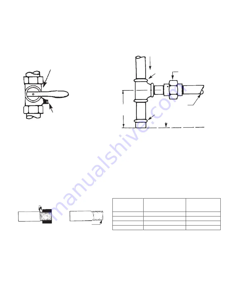
All piping must comply with local codes and ordinances or the National Fuel Gas Code ANSI Z223.1/NFPA No. 54. A sediment trap or
drip leg must be installed in the supply line to the burner. A union shall be installed in the gas line upstream from the con trol manifold
and downstream from the sediment trap or drip leg (See Figure 10). A 1/8” NPT plugged tapping port accessible for test gauge
connection shall be installed immediately upstream of the gas supply connection for the purpose of determining the gas supply
pressure to the burner. A manual shutoff valve shall be installed in the gas supply line external to the appliance (See Figure 9).
The gas line should be a separate supply direct from the meter to the burner. It is recommended that new pipe be used and loc ated so
that a minimum amount of work will be required in future servicing. The piping should be so installed as to be durable, substantial and
gas tight. It should be clear and free from cutting burrs and defects in structure or threading. Aluminum tubing should not be used for
the main gas supply. Joint compounds (pipe dope) should be used sparingly on male threads only and be approved for all gases.
Pipe Size
Inch (mm)
Effective Length of
Thread
Inch (mm)
Overall Length
of Thread
Inch (mm)
3/8 (9.525)
3/8 (9.525)
9/16 (14.29)
1/2 (12.7)
1/2 (12.7)
3/4 (19.05)
3/4 (19.05)
1/2 – 9/16 (14.29)
13/16 (20.64)
1 (25.4)
9/16 (14.29)
1 (25.4)
FIGURE 11: PROPER PIPING PRACTICE
It is recommended that tables 5, 6, and 7 be used to determine the size pipe to use from the meter to the burner. The building structure
should not be weakened by installation for the gas piping. The piping should not be supported by the other piping, but should be firmly
supported with pipe hooks, straps, bands or hangers. Butt or lap welded pipe should not be bent.
Note: Each elbow, union, and tee
adds approximately 2.5 feet of pipe.
The gas piping should be so installed so as to prevent an accumulation of condensation and it must be protected against freezing. A
horizontal pipe should be pitched so that it grades toward the meter and is free from sags. The pipe should not be run throug h or in an
air duct or clothes chute. The appliance and its individual shutoff valve must be disconnected from the gas supply piping system during
any pressure testing of the system at test pressure in excess of 1/2 psig (3447 PaG). The appliance must be isolated from the gas
1/8” NPT
Plugged Tapping
Pressure Gauge Port
FIGURE 9: MANUAL SHUT OFF
VALVE AND PRESSURE TAP
Direction of Flow
Tee
Union
Control Manifold
Pipe Cap
3” Minimum
(76.2mm)
Location of union and drip leg for connecting
conversion burner to house piping.
Manual Shutoff Valve
FIGURE 10: PIPE UNION AND FITTINGS
2 Imperfect
Threads
Leave 2 end
threads bare
Floor Level
Содержание P250 series
Страница 35: ...35 FIGURE 23 WIRING DIAGRAMS FOR GAS BURNER WITH DIRECT IGNITION FENWAL...
Страница 36: ...36 FIGURE 24 WIRING DIAGRAMS FOR GAS BURNER WITH ELECTRONIC PILOT HONEYWELL...
Страница 37: ...37 FIGURE 25 WIRING DIAGRAMS FOR GAS BURNER WITH ELECTRONIC PILOT NO T STAT...
Страница 38: ...38 FIGURE 26 WIRING DIAGRAMS FOR GAS BURNER WITH ELECTRONIC PILOT FENWAL...
Страница 46: ...46 NOTES...


