


19
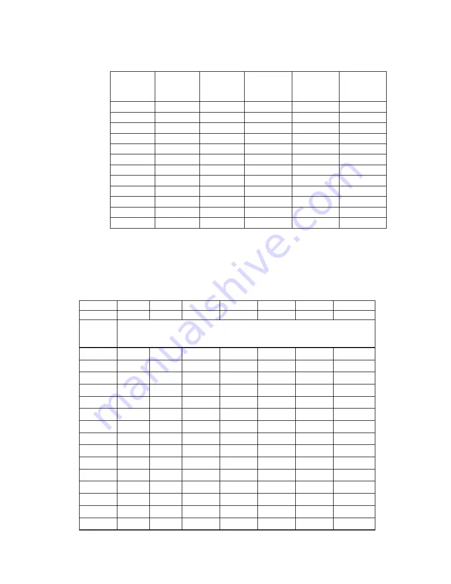
Table 1: Pipe Sizing Chart for Natural Gas (0-0.5 psi) with Straight Schedule 40 Metal Pipe
The following chart is based on
0-0.5 psi
inlet pressure, specific gravity of
0.6
, and a pressure loss of
0.5”
w.c..
Maximum Capacity of Pipe Size in Btu/hr
Length of
Pipe (ft)
1/2”
3/4”
1”
1 1/4”
1 1/2”
10
175,000
360,000
680,000
1,400,000 2,100,000
20
120,000
250,000
465,000
950,000
1,460,000
30
97,000
200,000
375,000
770,000
1,180,000
40
82,000
170,000
320,000
660,000
990,000
50
73,000
151,000
285,000
580,000
900,000
60
66,000
138,000
260,000
530,000
810,000
70
61,000
125,000
240,000
490,000
750,000
80
57,000
118,000
220,000
460,000
690,000
90
53,000
110,000
205,000
430,000
650,000
100
50,000
103,000
195,000
400,000
620,000
150
40,000
84,000
160,000
325,000
500,000
200
35,000
72,000
135,000
280,000
430,000
Table 2: Pipe Sizing Chart for LP
(11” w.c.)
with Straight Schedule 40 Metal Pipe
The following chart is based on
11” w.c.
inlet pressure and a pressure drop of
0.5” w.c..
Special use:
Piping sizing between single or second stage (low pressure regulator) and appliance.
Maximum Capacity of Pipe Size in Btu/hr
Pipe Size
1/2”
3/4”
1”
1 1/4”
1 1/2”
2”
3”
Actual ID
0.622
0.824
1.049
1.38
1.61
2.067
3.068
Length of
Pipe
(feet)
Maximum Capacity in Btu/hr
10
291,000 608,000 1,145,000 2,352,000 3,523,000 6,786,000 19,119,000
20
200,000 418,000
787,000
1,616,000 2,422,000 4,664,000 13,141,000
30
160,000 336,000
632,000
1,298,000 1,945,000 3,745,000 10,552,000
40
137,000 287,000
541,000
1,111,000 1,664,000 3,205,000
9,031,000
50
122,000 255,000
480,000
984,000
1,475,000 2,841,000
8,004,000
60
110,000 231,000
434,000
892,000
1,337,000 2,574,000
7,253,000
80
94,000
197,000
372,000
763,000
1,144,000 2,203,000
6,207,000
100
84,000
175,000
330,000
677,000
1,014,000 1,952,000
5,501,000
125
74,000
155,000
292,000
600,000
899,000
1,730,000
4,876,000
150
67,000
140,000
265,000
543,000
814,000
1,568,000
4,418,000
200
58,000
120,000
227,000
465,000
697,000
1,342,000
3,781,000
250
51,000
107,000
201,000
412,000
618,000
1,189,000
3,351,000
300
46,000
97,000
182,000
373,000
560,000
1,078,000
3,036,000
350
42,000
89,000
167,000
344,000
515,000
991,000
2,793,000
400
40,000
83,000
136,000
320,000
479,000
922,000
2,599,000
Содержание HSG200
Страница 30: ...30 Figure 20 Flame Current Measurement Top Wayne control Bottom Honeywell control...
Страница 48: ...48 Figure 29 continued Junction Box Assemblies Exploded Figure 30 Motor Assembly Exploded...
Страница 49: ...49 Figure 31 Gun Assembly Exploded Figure 32 HSG Series Burner Exploded...
Страница 50: ...50 Figure 33 Outer Dimensions of HSG Series Burner 13 2 335 mm REF 7 7 in 195mm 7 in 178 mm 15 25 in 377 mm...
Страница 52: ...52 NOTES...


