background image

60 

SmartSensor V User Guide

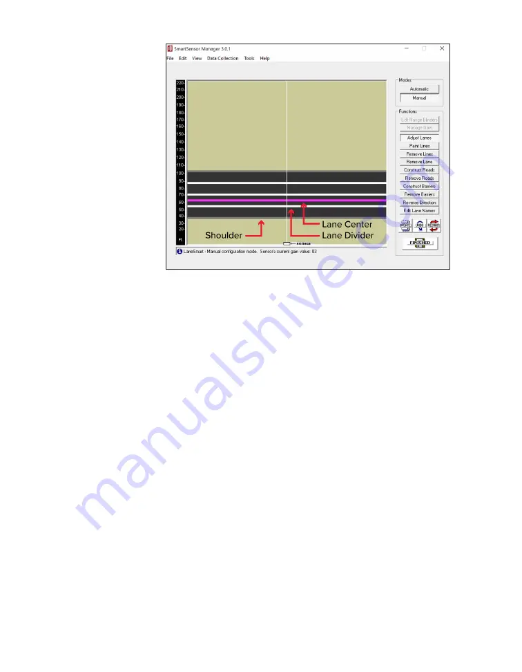
Figure 53. 

Adjusting lanes

Adding lane dividers

Click 

Paint Lines

.

Click in paved (black) areas to add new lane dividers. This 

allows you to create new lanes.

Removing a lane divider

Click 

Remove Lines

.

Click a lane divider to delete it.

Removing a lane

Click 

Remove Lane

.

Click on a lane to remove the entire lane.

Adding a road

Click 

Construct Roads

.

Click anywhere in the background (khaki) area to insert a new 

road.

Click 

Adjust Lanes

, and widen the road as desired.

Add and adjust lanes and lane dividers as needed.

Note.

 SmartSensor 

Manager allows 

a maximum of 

eight lanes.

Содержание SmartSensor V

Страница 1: ...SmartSensor V USER GUIDE...

Страница 2: ...SmartSensor V USER GUIDE Provo Utah 801 734 7200 www wavetronix com...

Страница 3: ...that the FMCW Traffic Radar SmartSensor V part number 101 0415 is in accordance with the 2004 108 EC EMC Directive The device has been designed and manufactured to the following standards IEC EN 60950...

Страница 4: ...ing the sensor to the mount 17 Aligning the sensor to the roadway 19 Applying silicon dielectric compound 19 Connecting the cable 3 INSTALLING POWER SURGE PROTECTION AND COMMUNICATIONS 21 Installation...

Страница 5: ...hooting latency issues 6 CONFIGURING SENSOR SETTINGS 46 Sensor information 47 Viewing sensor info 48 Sensor Settings 48 Saving and restoring sensor settings 49 Changing the General tab settings 51 Cha...

Страница 6: ...ging events 71 Understanding Event and Actuation mode 71 Verifying lanes using the event counter 72 The Interval Data screen 72 Understanding the Interval Data screen 73 Editing interval bin size 73 L...

Страница 7: ......

Страница 8: ...r selecting a mounting location for install ing and configuring a SmartSensor V To find the instructions for specific tasks see the table of contents If your questions aren t answered in this guide vi...

Страница 9: ...se devices preassembled and prewired in pole mount boxes and cabinet backplates available from Wavetronix Service information Don t try to service or repair this unit none of its components or parts a...

Страница 10: ...ing where to mount Figure 2 The V s radar footprint The SmartSensor V is a side fire radar detector that provides per lane vehicle volume average speed occupancy For best performance make sure the lan...

Страница 11: ...timing after a vehicle passes in front of the sensor there s a slight delay before the data for that vehicle is sent from the sensor In a time sensitive application like supplying a variable message s...

Страница 12: ...29 21 18 29 30 22 19 30 31 22 19 31 32 22 19 32 33 23 19 33 34 23 19 34 35 23 20 35 36 23 20 36 37 23 20 37 38 24 21 38 39 24 21 39 40 25 22 40 41 25 22 41 42 26 22 42 43 26 22 43 44 27 23 44 45 27 2...

Страница 13: ...6 7 7 0 5 8 4 9 7 0 7 3 5 8 4 9 7 3 7 6 6 1 5 2 7 6 7 9 6 1 5 2 7 9 8 2 6 4 5 5 8 2 8 5 6 4 5 5 8 5 8 8 6 4 5 5 8 8 9 1 6 7 5 8 9 1 9 4 6 7 5 8 9 4 9 8 6 7 5 8 9 8 10 1 7 0 5 8 10 1 10 4 7 0 5 8 10 4...

Страница 14: ...ased accuracy For best results choose the mounting height in the Height column in the table If you can t just keep it somewhere in the acceptable range Occlusion and multipathing These are two problem...

Страница 15: ...n problems Move the sensor higher on the pole keeping it within the rec ommendations in the mounting guidelines table Move the sensor to another spot on the freeway if possible away from obstructions...

Страница 16: ...problems Move the sensor if possible make sure it is separated from overhead signs overpasses tunnels parallel walls etc A 30 ft 9 1 m lateral separation would be ideal but even just a few feet can ma...

Страница 17: ...the slots on the mount 2 Position the mount on the pole at the height you chose from the mounting table in the previous chapter 3 Point the head of the mount toward the middle of the lanes you want t...

Страница 18: ...the sensor s backplate with the holes in the mount 2 Make sure the large 10 pin connector at the bottom of the unit is pointing towards the ground 3 Push the bolts through the mount holes 4 Place the...

Страница 19: ...incorrect left and correct right 2 If the sensor is installed on a road with an uphill downhill grade rotate the sensor so that the bottom edge matches the grade of the road this will require the purc...

Страница 20: ...pound on the connector at the base of the sensor Connecting the cable Figure 12 Cable run through pole left and through conduit right 1 Insert the cable connector into the sensor connector Be aware th...

Страница 21: ...s you to create a drip loop as shown above and gives you something to work with should you someday need to move the sensor to a different spot on the pole 4 If there s excess cable don t cut it as you...

Страница 22: ...an installation where the sensor cable runs down the pole to the pole mount box and to nowhere else Power comes from solar a battery or a power line that runs straight to the pole communications are...

Страница 23: ...CTS RTS GND 485 485 GND DC DC L N G Figure 14 Standard Preassembled Cabinet pole mount box Note This section assumes you are using the Standard Preassembled Cabinet from Wavetronix If you bought indi...

Страница 24: ...dard Preassembled Cabinet to the pole Lightning Surge Protection Wavetronix Protected Protected Click 200 RS 485 RS 232 DCE 110 VAC SmartSensor GND GND RD TD CTS RTS GND 485 485 GND DC DC L N G G L Fi...

Страница 25: ...D GND RD TD CTS RTS GND 485 485 GND DC DC L N G G L GND GND RD TD CTS RTS GND 485 485 GND DC DC Figure 17 Connecting sensor cable to terminal blocks 6 Insert the sensor cable the pigtail cable coming...

Страница 26: ...C converter The Click 200 which is a lightning surge protector This device is where the sensor cable is landed via the terminal blocks It protects the rest of the pole mount box from surges coming fro...

Страница 27: ...t Setting up the pole mount box Lightning Surge Protection Wavetronix Protected Protected Click 200 RS 485 RS 232 DCE To SmartSensor GND GND RD TD CTS RTS GND 485 485 GND DC DC To Traffic Cabinet GND...

Страница 28: ...D GND RD TD CTS RTS GND 485 485 GND DC DC To Traffic Cabinet GND GND RD TD CTS RTS GND 485 485 GND DC DC GND GND RD TD CTS RTS GND 485 485 GND DC DC Figure 22 Connecting sensor cable to terminal block...

Страница 29: ...o terminal blocks 6 Insert one end of the homerun sensor cable the cable that runs to the traffic cabinet into the leftmost grip on the bottom of the box Twist the cable grip to tighten 7 Follow the i...

Страница 30: ...htning Surge Protection Wavetronix Protected Protected Click 200 RS 485 RS 232 DCE 110 VAC SmartSensor GND GND RD TD CTS RTS GND 485 485 GND DC DC L N G Figure 26 Mounting the backplate in the cabinet...

Страница 31: ...r cable This backplate is shipped from Wavetronix with the conductors in the cable already ter minated in a terminal block plug Insert this plug into the power terminal blocks 4 If for some reason the...

Страница 32: ...lant consisting of a circuit breaker AC surge protector and AC to DC converter located in the traffic cabinet Two Click 200 modules which are lightning surge protectors one at either end of the underg...

Страница 33: ...artSensor Manager SSM is software that lets you configure and interact with the SmartSensor V sensor It can only be installed on a PC Downloading and running SSM Figure 29 Finding the SSM download on...

Страница 34: ...Description Details Table of Contents Brings up table of contents for all help information available Click on a topic and then click Display Help Topic to view the help screen for that topic Much of...

Страница 35: ...nnecting to the Sensor SSM communication basics Figure 31 Connection screen SmartSensor Manager can connect to your sensors via a serial RS 232 or RS 485 modem or Internet IP address connection this m...

Страница 36: ...PC com port baud rate set tings radio button This will activate the Port and Baud Rate bps drop down lists Additional Response Wait Time Lets you change how long the software waits for a response befo...

Страница 37: ...modem settings Local Modem Settings If needed enter the initialization string and auto find command in their respective text fields Click Restore Defaults to return these functions to their default se...

Страница 38: ...settings as default The OK button saves the new settings and the Cancel button cancels the changes Making an Internet connection Figure 34 Internet connection window 1 On the main screen select the In...

Страница 39: ...e sensor to auto de tect the multidrop ID Time Synchronization Click the checkbox to have the Smart Sensor V automatically synchronize with the PC clock Click the checkbox near the bottom of the Advan...

Страница 40: ...e in YY format Algorithm Month Shows the month of the version s release in MM format as well as the operating mode this will appear as an S for side fire mode and an F for forward fire mode Day Applic...

Страница 41: ...n a multidrop network multiple sensors on the same bus or a simple sensor network single sensor on a bus This reflects the protocol settings that you chose in the Advanced Connection Settings window R...

Страница 42: ...ck OK to close the window Address book The address book can save connection information for both modem and Internet connections allowing you to access this infor mation later and connect quickly witho...

Страница 43: ...lected entries of your last opened address book Opening an address book using the connection window Figure 39 Opening the address book using the connection window Note If you access the address book v...

Страница 44: ...etails Select Enters a selected entry s information into the respective connection window When you are connected to a sensor the Select button will be disabled You ll be able to edit the address book...

Страница 45: ...error window Figure 41 Communication error window 1 If the sensor can no longer communicate with the sensor the Communication error window appears 2 If desired click Details to see communication erro...

Страница 46: ...munication error screen N A Response Timeout Displays the total number of milliseconds that SSM waited before timing out the requested operation N A Troubleshooting latency issues 1 If you retry multi...

Страница 47: ...46 SmartSensor V User Guide 6 Configuring Sensor Settings There are several ways to access and change sensor settings using SSM Sensor information Figure 43 Sensor Information window...

Страница 48: ...be changed Description Shows the description of the sensor and or the installation site This is set by going to Edit Sensor Settings and editing the Description field Location Describes the location...

Страница 49: ...hich version of DSP the sensor is operating on N A FPGA Shows which version of FPGA the sensor is operating on N A Sensor Settings Go to Edit Sensor Settings to view and change sensor options If no se...

Страница 50: ...guration file ssc on your computer This button can be used to back up your settings Open from Sensor Returns all settings to those currently saved on the sensor N A Save to Sensor Saves the changes yo...

Страница 51: ...SSHD protocol Enter an ID if your controller or backend system was originally configured for an RTMS model X3 sensor and is still expecting data in RTMS protocol Description Lets you create a descript...

Страница 52: ...feet of each other set each to its own RF channel Changing the Communication tab settings Figure 46 Communications tab Setting Description Details Baud Rates RS 232 Port Lets you set the baud rate fo...

Страница 53: ...ssion direction Exp A B Lets you set how long the sensor will wait before responding to a received message shown in milliseconds These ports are currrently not available for use Advanced Comm Register...

Страница 54: ...Exp A and Exp B are currently not available for use Data Type Lets you choose the type of data that is pushed over the port SS Bin Data interval data SS Event Data per vehicle data SS Actuation presen...

Страница 55: ...r local computer Automatically adjusts the sensor to accomodate for local computer timezone and daylight saving time settings N A Sync Performs a one time sync of the sensor to the PC s UTC time N A S...

Страница 56: ...Chapter 7 Configuring Lanes 55 7 Configuring Lanes Automatic lane configuration Figure 48 Lane Configuration screen...

Страница 57: ...ange Blinders or Manage Gain buttons do so now For more information on these options see the following sections 4 Click the Restart button in the bottom right corner of the screen 5 When the pop up ap...

Страница 58: ...ed roadways will be cleared 2 Click on one of the range blinders and drag its edge to the desired range refer to the range markers on the left side of the screen 3 Repeat Step 2 for the other range bl...

Страница 59: ...the more returns you can get You can increase the gain if you re looking at traffic and you re not seeing any signal back The software will automatically adjust the gain as needed How ever if you re i...

Страница 60: ...configuration options 1 Go to Edit Lane Configuration 2 Click the Manual button on the right side of the screen most of the buttons in the toolbar on the right of the screen will change from gray to b...

Страница 61: ...der 1 Click Remove Lines 2 Click a lane divider to delete it Removing a lane 1 Click Remove Lane 2 Click on a lane to remove the entire lane Adding a road 1 Click Construct Roads 2 Click anywhere in t...

Страница 62: ...e direction of the center lane 1 Click Reverse Direction 2 Click on a lane to reverse its direction 3 Repeat step 2 until all lanes reflect the actual direction traveled by detected vehicles Definitio...

Страница 63: ...associated with the next closest lane and so on To map the lanes in a different order enter the sign followed by a unique number character between 1 and 8 Unused lanes do not need to be named The othe...

Страница 64: ...ils Update Saves all manual changes This button allows you to save without closing the settings screen Undo Removes any unsaved manual changes N A Restart Erases all manual changes that have been made...

Страница 65: ...ure 57 Data Collection tab Setting Description Details Default Loop Size Spacing Makes your system emulate a system with inductive loops These settings are read by a Click contact closure device which...

Страница 66: ...tiple detections but too much can lead to multiple vehicles being detected as a single vehicle Lane Setup Lane Name Allows you to change the name of the lane This can also be changed in the Lane Confi...

Страница 67: ...each lane s loop spacing to that of the default loop spacing Adjust this setting if speeds are consistently too high or too low Ext Time Lets you set whether extension time settings affect a given la...

Страница 68: ...the configuration before any filtering has been applied The Filtered row is the threshold level that is set after the sampling and filtering of events and background noise has been completed If the se...

Страница 69: ...Finished on the Lane Configuration screen The Traffic Event Data screen View Event Counter Event Logging View Event Log Mode Interval Data Figure 59 Traffic Event Data screen Note If the connection s...

Страница 70: ...Event Data screen event logging will have been turned off View Event Log Opens the current event log file in a text editor such as Notepad The event log file breaks down each event and reports back th...

Страница 71: ...acters that describe the lane Duration 2 5ms The number of 2 5 ms ticks that elapsed while the vehicle was in the sensor s detection zone MPH This represents the speed of the vehicle displayed either...

Страница 72: ...the detection zone In Actuation mode the three leftmost icons are inactive This mode can also be used to verify true presence information Verifying lanes using the event counter 1 Set up a way to obse...

Страница 73: ...eld and the buttons to set a new interval length Interval Data Display Shows data collected for the last interval Interval data updates in real time Synchronize Time Synchronizes the sensor s time to...

Страница 74: ...interval data 1 Click the Interval Data Logging button to turn on interval logging 2 If there s no file you ll be prompted to create a new one 3 When you re finished logging data click the Interval D...

Страница 75: ...per hour mph or kilometers per hour kph depending on your settings Occupancy Displays the percentage of time vehicles occupied the sensor s detection zone during the selected interval Classification...

Страница 76: ...Setting Up and Downloading Sensor Data 75 9 Setting Up and Downloading Sensor Data Once you ve set up your sensor and lanes you can collect interval data Data collection setup Figure 63 Data collecti...

Страница 77: ...you want to stop collecting interval data when the sensor s flash memory is full Flash Storage Time Shows how long until the sensor s storage reaches capacity Use this to know how much storage space...

Страница 78: ...to 246 of the most recent interval data records This type of storage is temporary because SRAM is volatile its contents will be lost if the sensor s power supply is interrupted The sensor s flash mem...

Страница 79: ...s only the interval data that was recorded after the indicated date and time The number of lanes per record is determined by the number of lanes cur rently configured on the sensor Error Recovery Retr...

Страница 80: ...new file name in the File name textbox and click Open This creates a file that will be used to log data Filling data logs After creating a new data log you need to tell the software to begin logging...

Страница 81: ...xported file immediately click the Open 3 Card export file when finished checkbox 8 Click Finish to create the 3 Card file SmartSensor Manager will take the entered information and format the file acc...

Страница 82: ...l not persist after a power cycle Select the Store in Flash Memory option to move data from SRAM to the sensor s flash memory which will protect it from being overwritten The Flash Interval setting is...

Страница 83: ...82 SmartSensor V User Guide 10 Using Tools The Tools menu allows you to view and send messages to and from the sensor as well as to upload firmware Hyperterminal Figure 68 Hyperterminal...

Страница 84: ...ts information all at once after pressing Enter Transmit character as each is typed Automatically trans mits each character as it is typed 4 Press Enter on your keyboard The response will appear in th...

Страница 85: ...mputer 1 Select a type of upload 2 Click Browse and then select a firmware file hex on your computer 3 Click UPLOAD to transfer the firmware to the sensor Note Before using something other than the mo...

Страница 86: ......

Страница 87: ...69 72 73 75 79 81 log 70 72 73 79 80 per vehicle 53 presence 53 push 52 53 settings 81 storage See also storage type 53 date 53 54 78 79 default 35 36 37 38 41 52 58 62 64 66 71 76 download 76 77 78...

Страница 88: ...9 10 13 14 65 71 range 10 13 81 blinders 56 57 response delay 45 52 restore 36 49 RF channel 14 51 RS 232 25 31 34 48 51 52 RS 485 10 25 31 34 48 51 52 S semitrucks 13 serial adapter 35 connection 34...

Страница 89: ...88 SmartSensor V User Guide volume 56 69 74 76 W warranty 8 21 25 31 wireless 10 21...

Страница 90: ...www wavetronix com...

Отзывы: