2 of 20
WX-501-0517 • 05.22
LEDs
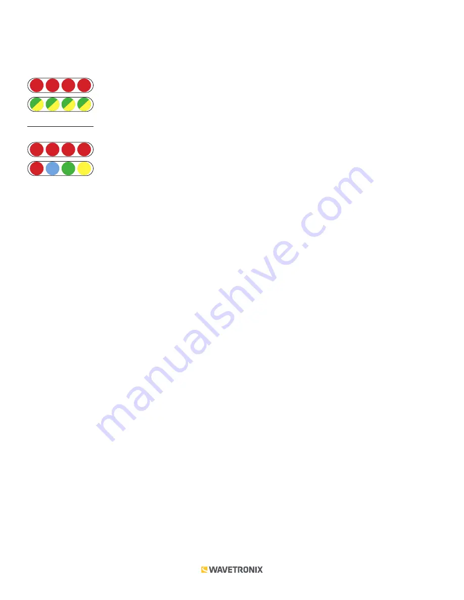
The faceplate of the Click 110 has four banks of LEDs. The top bank is used for detection indication, the second bank
for fault indication, the third for menu indication, and the fourth for menu indication as well as operation states.
Detection
1
2
3
4
Fault
Menu
PWR MF
TD
RD
1
2
3
4
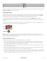
The detection indicator LEDs consist of four red LEDs numbered 1–4, each representing a channel (see the figure
above). An illuminated LED indicates the presence of a vehicle. These indicators are dedicated to detection and
have no other display purposes.
The fault indicator LEDs consist of four dual-color (green/yellow) LEDs numbered 1–4, each representing the
channel with the corresponding number.
■
Illuminated green LED –
Indicates a no-fault condition.
■
Illuminated yellow LED –
Indicates a fault condition which has existed for less than one minute.
■
Extinguished LED –
Indicates a fault condition which has existed for more than one minute.
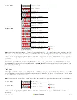
The menu indicator LEDs include two rows of LEDs (see the figure above). The lower row contains Level 1 indicators,
while the upper row contains Level 2 indicators. Each level consists of four LEDs numbered 1–4 (left to right). Level
1 LEDs display which menu is active. These Level 1 LEDs are dual-purpose, each indicating both menu selection as
well as a normal operation state when not in Menu mode. The normal operation state functions include:
■
Red (PWR) –
Indicates the presence of power to the device.
■
Blue (MF) –
Illuminates when the master fault output is in the no-fault condition. The LED is extinguished in the
fault condition.
■
Green (TD) –
Indicates serial communication transmit data (from the Click 110) on either RS-485 bus 1 or RS-485 bus 2.
■
Yellow (RD) –
Indicates serial communication receive data (to the Click 110) on either RS-485 bus 1 or RS-485 bus 2.
Level 2 LEDs display configuration options. All level 2 LEDs are red. These LEDs are dedicated to menu operation,
and are extinguished when the menu is not active.
Push-buttons
The faceplate of the Click 110 features two push-buttons. The upper push-button, labeled
Mode Switch
, is used to
cycle through and select menu and configuration options.
The lower push-button, labeled
Reset
, will reboot the Click 110. The Click 110 can be rebooted in any of three
ways: via the reset switch, from the outstation via the 64 way DIN 41612, or by power cycling the device. A reboot
is the only way to clear a latched fault condition. To reboot using the reset switch, simply press and release the
push-button.


