Wave Central AXTX1 Скачать руководство пользователя страница 6


6


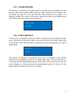
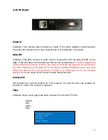
1.4.1   Frequency Selection 

If Frequency is selected and the NAV button is pushed once, the display will enter 
frequency edit mode. Using the NAV button, left, right, up and down the frequency can 
be entered one digit at a time then the NAV button pushed once to select. If a 
frequency outside of the range of the radio is selected, there will be an ERROR report 
and the ODU will revert to the previous frequency. 


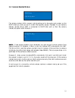
1.4.2   Power Output Level 

If Power Level is selected and the NAV button is pushed once, the display will enter 
power edit mode. Using the NAV button, left, right, up and down the power output level 
can be chosen. When the NAV button is pressed once, the selected power level will be 
programmed. 


When either the frequency or the power level is set, on completion of the TX-ODU 
programming, the display will revert to the Radio Status Page. Camera control will not 
be restored until the Radio Status page has been exited. In the event the user does not 
exit the display, a 10 second time-out will automatically restore the unit to the Unit 
Status display and camera control will be restored. 


Radio Frequency 
  
462.78625 

Radio Power 
  
100mW 


Содержание AXTX1

Страница 1: ... AXTX1 Broadcast Camera Control Paint System Guide RCP TX IDU CAMERA TALLY INTERFACE UNIT AXTX1 Camera TX TX ODU Wave Central LLC 99 Garden Parkway Suite C Carlisle PA 1 888 736 9283 www wave central com ...

Страница 2: ...s simple to configure as per the diagram to provide camera control for up to 4 cameras on a single UHF channel The radio channel is programmable from 403 to 474 MHz via the daylight readable display using the navigation buttons provided The fourth component is the AXTX1 Broadcast Camera Transmitter with Camera Paint Data Receiver Figure 1 RCP TX IDU Figure 2 Camera Tally Interface Unit Figure 3 TX...

Страница 3: ...ime to control a maximum of 4 independent cameras In the case of the Sony control panel the ID Port number will be indicated on the panel in the Tally Display area Camera tally are interfaced via the camera tally interface Connectivity between the camera tally interface and the RCP TX IDU are Cat 5 or 6 ethernet cable connection the Red and Green Tally respectively The video switch tally control c...

Страница 4: ...he ODU Notification of a Tally to that port is indicated by R for RED Tally and G for GREEN tally 1 3 Manufacturing Status If the NAV button is pressed once the Camera manufacture menu can be seen By tipping the NAV button up and down different manufactures can be chosen and if the relevant license has been obtained selected When the desired manufacturer has been reached the NAV button is pressed ...

Страница 5: ...rogated and no cameras can be controlled This process is usually done during installation and should not normally be necessary during a program transmission Feedback from the TX ODU of the Frequency and Power level will be displayed and on the bottom line of the display the desired edit function can be selected between frequency and power level Main Menu Radio Radio settings Menu Disables camera c...

Страница 6: ... the NAV button is pushed once the display will enter power edit mode Using the NAV button left right up and down the power output level can be chosen When the NAV button is pressed once the selected power level will be programmed When either the frequency or the power level is set on completion of the TX ODU programming the display will revert to the Radio Status Page Camera control will not be r...

Страница 7: ...ted between the PC and the IDU If it is the first connection Windows will report installation of the COM port Note the COM port number allocated for example COM3 The driver required is supplied as part of Windows 7 otherwise it can be downloaded from ftp videosys no ip org Once the file has been downloaded and the USB connection made the file can be executed The file will test to see if there is a...

Страница 8: ...d legislation applicable to your working environment In any event the TX ODU should be placed such that there is a clear line of sight over the desired working area UHF signals can penetrate through some objects but operation distance can be severely impeded 2 1 Connections AC Power is supplied to the rear panel RCP TX IDU The data connection the TX ODU is by customer supplied ethernet Type B cabl...

Страница 9: ...9 3 AXTX1 Camera Control Unit Paint System 450 UHF RX Ant TX Antenna Figure 6 AXTX1 Right Side Figure 7 AXTX1 Front Panel 2 1 1 3 ...

Страница 10: ...ED voltage for Bi Level Tally indicator Data The camera control unit CCU connects to the camera using the supplied data cable This is a LEMO 4 pin female RS 232 date for CCU camera paint Thompson Grass Valley Paint The camera control unit CCU connects to the camera using the supplied data cable This is a Hirose 7 pin female RS 422 data for CCU camera paint Sony Audio 1 Audio 2 XLR Connectors x2 An...

Страница 11: ...ived a carrier but does not indicate the presence of valid data If the LED is flashing but the Data RX on the display indicates ERROR this can mean that either the camera ID is set incorrectly or there is no valid data for the ID currently selected Or it can mean the RF signal is being interfered with Camera ID Will indicates the current Camera ID This relates to the port the user has selected on ...

Страница 12: ... RCP TX IDU on CCU 1 and the camera number is set to camera 2 there will be no camera control at all and the main status will indicated Data ERROR This is because there is no valid data for this camera number receiver However if there are two Camera RCP s connected to CCU port 1 and CCU port 2 and the camera number is set to 3 or 4 the same result will be observed If the camera number were set to ...

Страница 13: ...panel RCP TALLY Dual Ethernet Type B wiring for RED and GREEN USB Type B Used for firmware updates via computer 120 240 V AC Input TX ODU DATA PWR Ethernet Type B wiring Antenna SMA female connector TALLY INTERFACE USB Ethernet Type B wiring RED USB Ethernet Type B wiring GREEN Push Connectors Camera 1 2 Pair Red Black RED GREEN Camera 2 2 Pair Red Black RED GREEN Camera 3 2 Pair Red Black RED GRE...

Страница 14: ...e audio connector audio input Audio 2 XLR female audio connector audio input HD SDI BNC HD SDI Video in RCP TX IDU Power In 120VAC 60 Hz 25 Watts DATA Ethernet Type B wiring CCU DB9 female connector Tally Dual Ethernet Type B wiring USB USB Type B TX ODU Power In 6 17VDC DATA PWR Ethernet Type B wiring Antenna SMA female connector FCC ID MRBSATEL TA13G RF Frequency 403 474 MHz Programmable from fr...

Отзывы: