
14
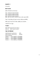
Appendix 2
Technical Specifications
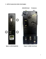
AXTX1 Camera Broadcast Transmitter with Paint
Includes: CCU Paint 403 – 474 MHz UHF Data Receiver)
RX RF In
SMA female
TX RF Out
N type connector
HDMI
HDMI type A connector, video and audio input
External Tally Out
1/8” Phone jack (Ring tip sleeve)
Data
LEMO 4 pin female RS-232 data to camera CCU
Paint
Hirose 7 pin female RS-422 data to camera CCU
Audio 1
XLR female audio connector, audio input
Audio 2
XLR female audio connector, audio input
HD/SDI BNC
HD/SDI
Video
in
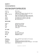
RCP-TX-IDU
Power In
120VAC 60 Hz 25 Watts
DATA
Ethernet
Type
B
wiring
CCU
DB9
female
connector
Tally
Dual - Ethernet Type B wiring
USB
USB
Type
B
TX – ODU
Power In
6 – 17VDC
DATA PWR
Ethernet Type B wiring
Antenna
SMA
female
connector
FCC
ID MRBSATEL-TA13G
RF
Frequency
403 – 474 MHz Programmable from front panel
Channel
B/W
12.5
KHz
Modulation
GMSK
(
Gaussian Minimum Shift Keying
)
TX
Power
100/200/500/1000mW
Selectable front panel RCP-TX-ODU
Data Interface
RS485 9600 baud
**User Guide Ver. 1.5 March 2015


