© 2020 tekmar 087_D - 02/20
3 of 8
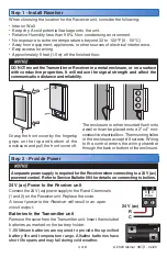
When choosing the location for the Receiver unit, consider the following:
• Interior Wall.
• Keep dry. Avoid potential leakage onto the unit.
• Relative Humidity less than 90%. Non-condensing environment.
• No exposure to extreme temperatures beyond 32 to 122°F (0 - 50°C)
• Away from equipment, appliances, or other sources of electrical interference.
• Easy access for wiring
• Approximately 5 feet (1.5 m) off the finished floor.
Step 1 - Install Receiver
Grasp the front cover by the fingertip
grips on the top and bottom of the
enclosure and pull the front cover off.
The enclosure is either mounted flush onto
a wall or it can be placed onto a 2" x 4" non-
conductive electrical box. The mounting holes
in the enclosure accept #6 screws. Wiring
to the control enters the wiring chamber
through the back or bottom of the enclosure.
Step 2 - Provide Power
1
Power
2
C
R
24 V (ac)
R
C
Batteries in the Transmitter unit
Remove the cover from the Transmitter unit. Insert the included
batteries as marked on the battery holder.
1.5V lithium batteries are required to provide the specified
battery life and temperature range. Alkaline batteries have
short life spans and may fail during cold weather.
A separate power supply is required for the Receiver when connecting to a 24 V (ac)
powered control. Refer to Service Bulletin 094 for details on connecting to boilers.
DO NOT mount the Transmitter or Receiver in a metal enclosure, or on a surface
with conductive properties. It will reduce the signal strength and affect the
communication distance and reliability.
24 V (ac) Power to the Receiver unit
Connect the 24 V (ac) power supply to the R and C terminals
(1 and 2) on the Receiver unit. Replace the cover.
A loss of power to the Receiver will result in an open
circuit output.


