background image

GB 


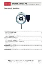
5.3.2  Single circuit hydraulic installation: Parameter #4=SEP 


Security Contact thermostat 


Optionnal Return sensor 

(Used when no RF thermostat is installed) 


Supply water sensor 


 Main pump 


Mixing 3 way valve 


Boiler control 


Water chillers signal 


Heating Mode 

Cooling mode 

Heating demand output driving the boiler or 
Stage 2 heating (if PE=yes) 

Active (Contact closed) when the pump 1 is 
active or when there is a domestic hot water 
demand or PE=Yes with Ext Temp < PE t 

Always OFF (Contact opened) 

Cooling demand output driving a water chiller 
 

Always OFF (Contact opened) 

Active (Contact closed) when the pump 1 is 
active 

Pump 1 output with wired TH1 thermostat 

Active if the thermostat is in heating demand 

Active if the thermostat is in cooling demand 

Pump 1 output with RF TH1 thermostat 

Active if the thermostat is in heating demand 

Active if the thermostat is in cooling demand 


5.3.3  Dual circuit hydraulic installation: Parameter #4=2P.1 or 2P.2 with wired thermostat: 

(*)  
2P.1 with wired thermostats: Thermostat 2 for direct circuit is a non-reversible model (Contact when ambient temperature is below 
setpoint). In cooling mode, the climatic control will automatically reverse the contact information. 
 
2P.2 with wired thermostats: Thermostat 2 for direct circuit must be a reversible model (Contact when heat or cool demand). 
 

2P.1 or 2P.2 with wired thermostat 

Heating Mode 

Cooling mode 

Heating or cooling demand output informing the 
heat pump or Stage 2 heating (if PE=yes) 


Active (Contact closed) when the pump 1 or 
pump 2 is active for heating circuits (IN1=TH1, 
IN2=TH2) or PE=Yes with Ext Temp < PE t 

Active (Contact closed) when the pump 1 or 
pump 2 is active for cooling circuits (IN1=TH1, 
IN2=TH2) or PE=Yes with Ext Temp < PE t 

Pump 2 output 
 

Active (Contact closed) if heat demand on direct 
radiator circuit thermostat 2 

Active (Contact closed) if cold demand on direct 
radiator circuit thermostat 2 (*) 

Pump 1 output 

Active if the wired thermostat 1 is in heating 
demand 

Active if the wired thermostat 1 is in cooling 
demand 


Security Contact thermostat 


HeatPump 
signal 


Aquastat 


Pannel heater 
pump 2 


Supply water sensor 


 WFH Main pump1 


Mixing 3 way valve 


HP 

Содержание RCL-HC

Страница 1: ...GB 1 Climatic Control H C User Guide PPLIMW08157Ch EN wattswater eu ...

Страница 2: ...e shops approved by the manufacturer only The functionality of the control depends on the model and equipment This installation leaflet is part of the product and has to be obtained Subject to technical modification Table of content 1 Application 3 2 References Symbols and Abbreviations 3 3 Safety Instructions 3 4 Display 4 5 Installation and Electrical connections 4 5 1 ClimaticControl HC Install...

Страница 3: ... better understanding in this document references are used in the form of symbols and abbreviations which are described below Reference to further documents FlH Floor heating Important information and application hints RaH Radiant heating general Safety information or Important information about functions FRG Hydraulic control unit with pump and mixing valve OK button OK HKV Manifold Control butto...

Страница 4: ... for example FRG or FlowBox and if it is not attached to that unit by any installation plate or support it should be installed next to that unit Pay attention to the correct connection of the cables if the ClimaticControl HC is not installed directly on a hydraulic control unit but at some other place for the reason of better access Refer to the directions about this in section 5 2 Electric connec...

Страница 5: ...ed sensor Possible RF Outdoor sensor in option 3 Point actuator WATTS EVO2 Cooling output 230VAC 50Hz or P2 Pump 230 VAC 50 Hz Direct circuit L N Fig 5a Heating output Heating demand for the boiler Free contact N L N Option Optional connection temperature limiter TB option for pump1 only The connection is factory fitted with a cable bridge It must be removed if connecting TB Logical inputs o 2 o 4...

Страница 6: ... Yes with Ext Temp PE t Always OFF Contact opened Cooling demand output Pump 2 output driving a 3 way On Off valve to choose between Heating or cooling water Always OFF Contact opened HOT Always ON Contact closed COLD Pump 1 output with wired TH1 thermostat Active if the thermostat is in heating demand Active if the thermostat is in cooling demand Pump 1 output with RF TH1 thermostat Active if the...

Страница 7: ...1 with wired thermostats Thermostat 2 for direct circuit is a non reversible model Contact when ambient temperature is below setpoint In cooling mode the climatic control will automatically reverse the contact information 2P 2 with wired thermostats Thermostat 2 for direct circuit must be a reversible model Contact when heat or cool demand 2P 1 or 2P 2 with wired thermostat Heating Mode Cooling mo...

Страница 8: ...tic hot water demand through Aquastat input IN1 or IN2 OR PE Yes with Ext Temp PE t Active Contact closed when the pump 1 or pump 2 is active for cooling circuits OR PE Yes with Ext Temp PE t Pump 2 output Active Contact closed if heat demand on direct radiator circuit RF thermostat 2 Active Contact closed if cold demand on direct radiator circuit RF thermostat 2 Pump 1 output Active if the RF the...

Страница 9: ...p switches off after pump delay time PUMP System parame ters pump delay time WFHT BASIC WFHT LCD MILUX xxx 5 4 2 Direct circuit Panel Heater standard room thermostat wired type If a second circulation pump is installed and managed by the ClimaticControl HC Inst System param eters installation type 2P x you can install a second wired room thermostat to manage the working of the high temperature pum...

Страница 10: ... 1 C upper the setting temperature of the thermostat If a Milux RF Hygrostat is used the program feature See Chapter Error Reference source not found is deported on the thermostat user interface 5 4 4 Wireless room Hygrostat Water Floor thermostat trF1 If a radio frequency room Hygrostat is plugged in the flow temperature calculated on the basis of outdoor temperature and the curve flow temperatur...

Страница 11: ...e to the Wireless outside sensor the regulation will continue to work with the last value received from the out side sensor 5 4 7 Inputs functions In1 In2 If no wired thermostat is installed in the house you will have the possibility to use the two available inputs of your ClimaticControl HC for different functions Inst System parameters Input In1 In2 1 Input1 Inst System parameters Input HC You c...

Страница 12: ...The heating output will stay activated even if the aquastat have stopped the circulation pump To avoid problem in cooling mode if the storage tank is filled with cold water by heat pump the aquastat function will be automatically desactivated Inst System parameters Input C_b In case of mutizone regulation WFHC Master RF with Heat Cool function is installed you could use the input 2 to connect the ...

Страница 13: ...llation with 2 circulation pumps Under floor heating and panel heater In1 used to stop the pump when the heat storage is empty Inst Parameters menu In1 Aqu In2 used to stop the pump when the heat storage is empty Inst Parameters menu In2 Aqu In2 Immersion thermostat Use to stop the pump2 T C In1 Immersion thermostat Use to stop the pump1 T C Fig 12 Pump signal closed pump On WFHC Aquastat storage ...

Страница 14: ... ClimaticControl HC becomes lower than the actual tempera ture value because of rising outdoor temperatures If the actual value of the flow temperature falls below the preset value the pump will restart In this case to ensure a correct measure of the water temperature the pump will be start each 30min for a short time to measure the real temperature of water inside the hydraulic circuit To ensure ...

Страница 15: ...acted to the calculated water temperature willbe always adjusted on the both working mode of the CC HC 0 00 C 10 0 C by default For the operation of the circulation pump please refer to the section of COMFORT mode of operation REDUCED TEMPERATURE mode of operation Unlimited operation in REDUCED TEMPERATURE mode This is a constant mode of operation of the system The ClimaticControl HC adjusts the f...

Страница 16: ...e on the ClimaticControl HC Because in this case the regulation will not work in the correct way TIME AND DATE setting In this menu you can set the actual time and date as well as the day of the week Using the cursor select first and then press the OK key By keys or set the minutes confirm by pressing OK By keys or set the hour confirm by pressing OK By keys or set the day of the week press OK to ...

Страница 17: ...g the programming of the last day 7 the indication first switches to the program menu and in about 15 seconds back to If during programming no inputs are made within 20 seconds indication switches first to the program menu and in another 15 seconds it returns to The inputs were not stored Factory built in programs P1 P9 If you select any of the factory programs from P1 to P9 you confirm it by pres...

Страница 18: ...d to set the most important parameters for the operation of the system To access this menu keep the OK key pressed for 10 seconds in Comfort Auto Reduced modes The display shows as well as the preset curve for example Parameters are selected by pressing the or keys To change the parameters press ОК and using or change them To leave the menu goes to the parameter End and press the OK key ...

Страница 19: ...set above Cooling parameters 1 Cooling curve value see fig 7 supplied water T curve outside T 0 4 0 1 to 5 2 Maximum value of flow temperature in Cooling mode 30 C Lo 5 C 100 C 3 Minimum value of flow temperature in Cooling mode 15 C 1 Hi 1 C Remark The thermostat has the priority over the water law limits on the pump and cooling outputs Thus the 3 way valve will always follow the limits set above...

Страница 20: ...s mounted on the return pipe of the hydraulic circuit _ _ _ b AP 7 bGAP Boost function The incoming water temperature will be increased by 20 if the return temperature is less than calculated water temperature minus bGAP set ting Wret Wcal bGAP WCal 20 Press on the OK to view the instan taneous value of the return sensor Remark if no water return sensor is wired then this boost function is bypasse...

Страница 21: ...use th parameter is set to YES no Input1 not used nothing wired no th1 un adjustable no Aqu HC or C_b Aqu A water Aquastat contact is wired on Input1 If over temperature is reached contact open then Pump1 circulator is stopped and the mixing valve is closed HC A Heat Cool switching signal is wired on In put1 to manage the working mode of the in stallation contact between point 2 and In1 or phase s...

Страница 22: ...es Wired outside sensor is installed No Installation without outside sensor The regulation will work like a thermostat with a adjustable Wcal temperature injected on the circuit rF Wireless RF outside sensor is installed Yes No rF The following parameter is only available if no outside sensor is installed and the OUSE parameter is set to no _ _ _ OU t 14 Outside temperature This menu is used to fi...

Страница 23: ...rmanent ON OFF cycle of the pump when PWM thermostat is installed 030 For best use the duration should be 2xPWM cycle of the thermo stat 001 to 060 and above infinite delay the pump will be ON all the time 20 Manual mode or test function for valve drive respectively 2 3 way valve By pressing the key the valve drive opens The display shows OPEN and By pressing the key the valve drive closes The dis...

Страница 24: ...ing value for sensors To be checked with an ohmmeter with sensor unplugged Temperature C Resistance value Ohm Temperature C Resistance value Ohm 20 C 94 k 40 C 5 3 k 10 C 54 k 50 C 3 6 k 0 C 32 k 60 C 2 5 k 10 C 20 k 70 C 1 8 k 20 C 12 5 k 80 C 1 3 k 30 C 8 k 8 Technical Data Materials Measured temperature accuracy 0 1 C Operating temperature 0 50 C Flow temperature control range 0 100 C Regulatio...

Страница 25: ...e to incorrectly con nected valve drive reverse action Check the connection of the valve drive 5 2 2 3 Too low flow temperature due to incorrectly con nected valve drive reverse action Check the connection of the valve drive 5 2 2 4 Incorrect selected operation mode Select the correct mode of operation 2 5 When ClimaticControl HC operating in AUTO MATIC mode incorrect programming of built in or us...

Страница 26: ......

Страница 27: ......

Страница 28: ...PLIMF08157Ch EN ...

Отзывы: