6
Installation
1. Turn off gas or electric supply to the water heater.
2. Turn off the main water supply to pipes to be cut and drain the
house water pipes.
3. Open both hot and cold faucets.
4. Move the filter assembly into installation position.
• Be sure the floor under the water filter system is clean, level and
strong enough to support the unit.
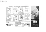
5. Plumb IN and OUT connections to and from filter.
• Be sure the incoming water supply is connected to the INLET
port of the valve.
• The valve body of the control is marked with arrows indicating
the proper flow direction.
• Connections are illustrated below.
6. Connect and route the valve drain line using rigid piping or hose.
Use the same size plumbing for the drain line as the fitting for
the drain connection. The smallest units have a
1
⁄
2
" connection,
the larger sized units have a
3
⁄
4
" connection. It is important to
use the same size plumbing as the connection to ensure proper
backwash flow. Properly secure the end of the drain line.
Note: Leave an air gap of at least 1
1
⁄
2
" between the end of the
drain plumbing and the drain point.
CAUTION: If making a soldered copper installation, do all sweat
soldering before connecting pipes to the bypass valve. Torch
heat will damage plastic parts.
CAUTION: When turning threaded pipe fittings onto plastic fit-
tings, use care not to cross-thread.
CAUTION: Use PTFE tape on all external pipe threads. Do not
use pipe joint compound.
CAUTION: Support inlet and outlet plumbing in some manner
(use pipe hangers) to keep the weight off of the valve fittings.
7. Place bypass valve in "bypass" position as shown below.
8. Fully open two (2) cold water faucets near the water filter.
9. Fully open the house main water shutoff valve. Observe a steady
flow from both faucets.
10. Close the cold water faucets.
11. Check plumbing work for leaks and fix immediately if any are
found.
12. Connect electrical power by plugging the transformer into a
(120 VAC) outlet.
13. Remove the cover from the valve. Press and hold the “Extra
Cycle” button until the flashing “BW” symbol appears in the
Parameter Display.
14. Unplug the valve when the “BW” symbol stops flashing and the
countdown timer appears. This keeps the valve in an extended
backwash for the initial startup.
15. Open the outlet bypass valve fully.
16. Open the inlet bypass valve slightly. Open the valve just until you
hear water flowing.
17. Observe the drain flow. It may take several minutes for the filter
vessel to fill up with water and begin to flow to drain.
18. After all the air is purged from the vessel and a steady drain flow
is observed, allow the unit to backwash for 2 hours with the inlet
valve open slightly.
19. Fully open the inlet bypass valve and allow the unit to backwash
for 30 minutes.
20. After 30 minutes, observe the drain flow. If the drain flow is clear
proceed to the next step. If the drain flow is still cloudy, allow it
to continue to backwash until it is clear.
Drain