Benchmark 5000-6000 Operation & Maintenance Manual
SECTION 4
– MAINTENANCE
OMM-0118_B
•
GF-203
•
5/9/2019
Technical Support
•
(800) 526-0288
•
Mon-Fri, 8 am - 5 pm EST Page 43 of 148
4.4.1 Air Eductor Air Pump Maintenance
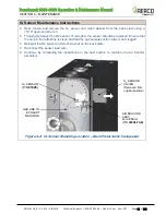
Benchmark 5000 and 6000 units contain an Air Eductor assembly, mounted on the opening in
unit’s back panel, just behind the 0
2
Sensor Cover (see Figure 4-2, above). It includes an air
pump, which draws an air sample from the combustion chamber, causing it to flow past the
Ox
ygen sensor mounted on the burner’s rear plate, ensuring its accuracy (see
Air Pump
Voltage
setting in the Operating menu, Appendix A1 for more information).
While the 0
2
Sensor Cover is removed, complete the instructions below to maintain the Air
Eductor’s air pump.
Air Pump Maintenance and Troubleshooting Instructions
1.
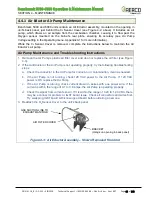
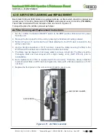
Remove the Air Pump’s plastic air filter cover and clean or replace the air filter (see Figure
4-3).
2. If the Air Eductor or the Air Pump is not operating properly, try the following troubleshooting
steps:
a. Check the connector to the Air Pump for corrosion or contamination, clean as needed.
b. If the Air Pump is not running, check 120 VAC power to the Air Pump. If 120 VAC
power is OK, replace the Air Pump.
c. If the Air Pump is running, check current drawn in series with one power wire. If the
current is within the range of 0.1 to 0.6 amps, the Air Pump is operating properly.
d. Check the signal from current sensor. If it is within the range of 0.20 to 1.20 VDC, there
may be a connector problem or IGST board issue. Check all connectors and wires first.
Try swapping IGST board with known good board before ordering a new one.
3. Reattach the O
2
Sensor Cover to the unit’s back panel.
Figure
4-3: Air Eductor Assembly
– Shown Removed from Unit
GAS SUCTION LINE TO
EXHAUST MANIFOLD
AIR FILTER COVER
BRACKET
(Hangs on opening in back panel)

