Benchmark 5000-6000 Operation & Maintenance Manual
SECTION 4
– MAINTENANCE
OMM-0118_B
•
GF-203
•
5/9/2019
Technical Support
•
(800) 526-0288
•
Mon-Fri, 8 am - 5 pm EST Page 39 of 148
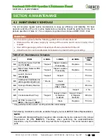
Kit
Kit P/N
Description
12 Month service
58025-11 Services Pilot Burner, Flame Rod & Condensate trap
24-Month Waterside/
Fireside service
58025-12
58025-11 plus: Burner, LWCO, Air Pump Filter & Air Filter
replacement
58025-15 Same as 58025-12 except clean (not replace) Air Filter
24-Month Waterside
service
58025-14 58025-11 plus: LWCO, replace Air Pump Filter & Air Filter
58025-16 Same as 58025-14 except clean (not replace) Air Filter
4.2 PILOT BURNER
The Pilot Burner (P/N
29700
) is located on the right-front of the Burner Plate. It contains an
ignition cable, the Pilot gas line connected to the bushing, and the Pilot Burner Rod (P/N
66100
), which should be inspected and/or replaced according the schedule in Table 4-1a.
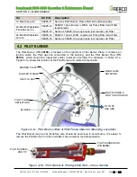
Figure 4-1a shows the location of the Pilot Burner and related components.
Figure 4-1a: Pilot Burner, Main & Pilot Flame Detector Mounting Locations
The Pilot Burner may be hot, therefore care should be exercised to avoid burns. It is easier to
remove the Pilot Burner from the unit after it has cooled to room temperature.
Figure 4-1b: Pilot Burner & Pilot Ignition Rod
–
Cross-Section
SIGHT GLASS
MAIN FLAME
DETECTOR
TO PILOT
GAS LINE
BLOWER
BLOWER FLANGE
BURNER PLATE
PILOT BURNER &
PILOT IGNITION ROD
PILOT FLAME
DETECTORS
PILOT BURNER
ROD TIP
PILOT BURNER ROD
(P/N
66100
)

