5
Servicing First and
Second Checks
Series 994/994RPDA
8" and 10" (200 – 250mm)
1. Slowly open all ball valves to relieve air and water pressure.
Loosen bolts on groove coupler and remove groove couple and
cover plate from valve body.
2.
#1 CHECK
Using a
9
⁄
16
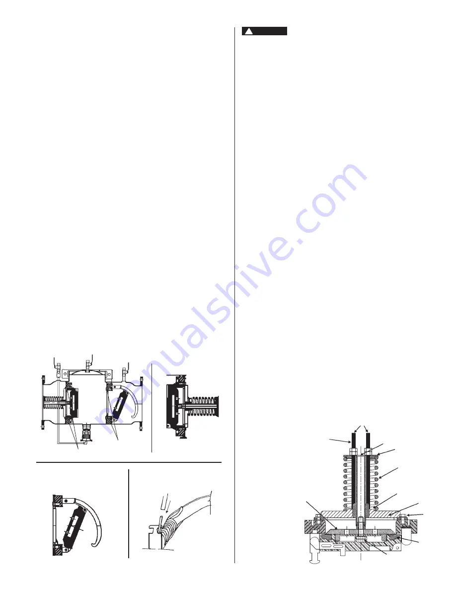
" socket wrench or nut driver, remove the four nuts
from the #1 check studs
(see fig. 1)
. Using two hands, place
them at 12 o’clock and 6 o’clock, wiggle the check assembly free.
Remove through access port with back of clapper first with spring
end down. Pull check assembly out of main body. Inspect seats
and clap per seal ing surfaces. (See page 6.)
#2 CHECK
After loosening bolts with a
9
⁄
16
" socket, remove bolts completely.
Using the centerline access bar, spin the check assembly from the
9 o’clock position to the 12 o’clock position, then (without letting
go of the ac cess bar) push the cam assembly slightly down stream
so that the clapper is now parallel to the valve body. Now bring
the check as sem bly through the check retaining wall. Leave the
check assembly par al lel to the valve body. Pull the check assem-
bly through the access port.
3. Using a
3
⁄
8
" nut driver or a piece of small diameter pipe, place
on the check arm torsion spring and move away from and move
away from and around the torsion spring retaining bracket so as
to relieve the tor sion spring tension. This will allow the check arm
to move free ly, en abling you to inspect the clapper face and check
seat. Thor ough ly clean the seat area and clapper sealing surfaces,
check arms, and O-rings for damage, nicks, and debris. If dam-
aged, in stall a new check as sem bly and or O-ring.
4. Before reinstallation of check assembly, thoroughly clean O-ring
groove and lubricate O-ring with F.D.A. approved lubricant.
Figure 1
Check Studs
Check Studs
Figure 3
#2 Cam-Check DC & RP
Figure 2
#1 Cam-Check RP
Figure 4
Removing Check Assemblies (Before servicing
be certain shutoff valves are closed)
1. After removing the first check from the backflow valve body, place
on a flat surface with the coil spring facing up.
2. In order to gain access to the seat and clapper rubber ring, you
must compress the spring (#3) that surrounds the clapper shaft
(#1). To do so, you must place the
3
⁄
8
" threaded rod through two
holes of the spring retaining plate #2.
3. After placing the
3
⁄
8
” all-thread rod through the spring retaining
plate, Screw the threaded rod into the holes (#4) at the base of
spider (#5 next to shaft). Be sure to use two nuts on the threaded
rod to tighten them into the holes. The depth of the threaded
holes should be approximately
1
⁄
2
". This operation will require you
to use two piec es of threaded rod (see drawing below).
4. Compressing the spring. To do so you need to loosen the top
3
⁄
8
”
nut and back it off without unthreading the threaded rod from the
spider. Place a box end wrench or crescent wrench on the
3
⁄
8
”
nut clos est to the spring retaining plate and tighten. Tighten both
thread ed and nut evenly; put a few turns on one threaded rod nut
and a few turns on the other.
5. During compression, the clapper will slowly move up, away from
the seat. To examine the seat, continue spring compression un til
the clapper has moved approximately 1" from the seat. This will
allow de bris to be removed and or the seat to be examined.
6. To unload the spring compression, loosen the all-thread and then
double nut the all-thread and unscrew the rod from the spider and
shaft base.
1. Shaft
2. Spring retaining plate
3. Spring
4.
3
⁄
8
” threaded hole (maintenance)
5. Spider
6. Spider retaining bolt
7. Seat ring
8. Clapper to shaft bolt
9. Seat ring retainer
1
2
3
4
5
6
3
⁄
8
- 16
var.
Threaded Rod
7
8
9
#1 Check
Valve 8" & 10"
(200 & 250mm)
DANGER
!
Use extreme caution when servicing the first check!
Servicing the
First Check
To inspect the seat and clean the seat and
clapper washer:
To disassemble the first check, you will need
the following:
• Two pieces of
3
⁄
8
" threaded rod (approximately 14" long)
• Adjustable crescent wrench
• Pipe wrench or channel lock pliers


