22
Need help or have any questions? Call us at 1-714-963-0329 or send us an email to [email protected]
❑
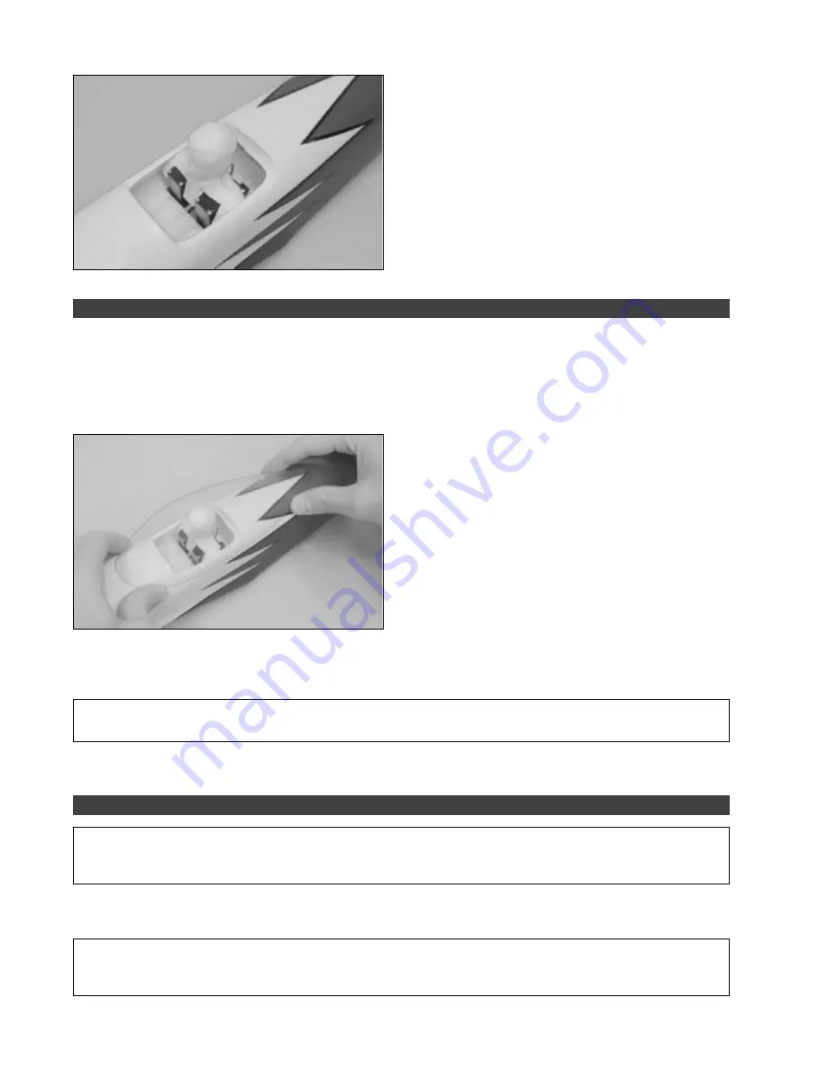
Using a pair of scissors, carefully cut the front and back
of the pilot bust to fit over the elevator and rudder servos. We
cut the pilot bust so that when the pilot was installed, the base
of the pilot was about 1/4" off the cockpit floor. This prevents
having to cut all the way through the top of the pilot.
❑
Glue the pilot bust to the top of the servos using a couple
dabs of 5 minute epoxy.
❑
Carefully cut out the base of the canopy along the outermost scribe line. The inner scribe line denotes the
canopy frame. If you want, you could paint the canopy frame before installing the canopy.
❑
Using 220 grit sandpaper with a sanding block, carefully sand the edges of the canopy smooth and straight.
☞
Be careful not to scratch the surface of the canopy when sanding its edges.
❑
Set the canopy onto the fuselage and align it. To position
the canopy properly, it should be centered over the middle of
the fuselage (when looking from the front) and the front edge
of the canopy should be 1-3/8" ahead of the cockpit opening.
STEP 2: INSTALLING THE CANOPY
❑
When satisfied with the fit and alignment, carefully glue the canopy into place using a thin bead of Pacer Formula 560
Canopy Glue. Use pieces of masking tape to hold the edges of the canopy firmly in place and remove any excess adhesive
using a paper towel soaked with
water.
✦
✦
✦
✦
✦
IMPORTANT
✦
✦
✦
✦
✦
Do not use C/A to glue the canopy into place. C/A will damage the clear plastic and when it dries will
leave a white "fog" inside the canopy.
☞
As an alternative to using glue, you could secure the canopy into place using 1/4" wide colored striping tape.
✦
✦
✦
✦
✦
IMPORTANT
✦
✦
✦
✦
✦
To minimize current loss, it is imperative that you remove the stock Tamiya connector likely preinstalled
on your ESC and flight battery, and replace it with a high-quality connector, such as a Dean's Ultra-Plug. Failure to do
this can cause a loss of power and result in a poor flying airplane.
❑
Carefully solder the positive and negative motor wires to the motor wires on your ESC, being careful that the polarity
is correct. Make sure to use heat-shrink tubing to insulate the solder joints.
✦
✦
✦
✦
✦
IMPORTANT
✦
✦
✦
✦
✦
We strongly suggest removing the motor plugs on the motor and the motor plugs that are likely
preinstalled on your ESC and soldering the motor wires directly to the motor wires on your ESC. Bypassing the plugs will
prevent any chance of current loss which could affect the amount of power to the motor.
STEP 3: INSTALLING THE ELECTRONIC SPEED CONTROL


