23
Visit our website at http://watt-age.globalhobby.com for information on other Wattage products
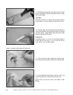
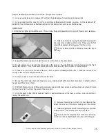
Step 2: Installing the Aileron Servos - Separate Servo Setup
❑
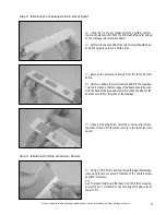
Using the tip of your modeling knife, remove the die-cut
piece from the middle of one aileron servo mounting board.
❑
Remove the protective backing from the board and stick
the board to the
bottom
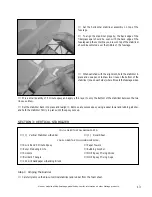
of the wing. The inside edge of the
board should be 1-1/8" out from the side of the wing mount
and the back edge of the board should be 2-3/4" in front of
the aileron hinge line.
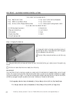
❑
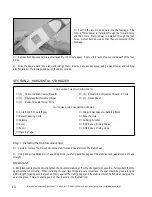
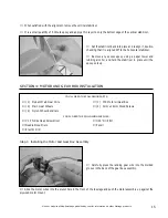
Install one servo into place using the same technique as
with the elevator and rudder servos. Use needle nose pliers
to pull the servo lead out of the hole in the wing mount.
IMPORTANT
The servo output shaft should be toward the leading edge of
the wing.
❑
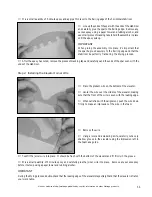
Using a modeling knife, cut away and remove the foam from within the cutout in the mounting board.
❑
Repeat the procedures above to install the second aileron servo into the other half of the wing.
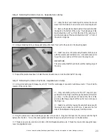
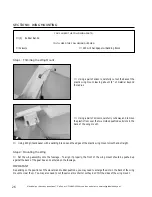
Step 3: Installing the Aileron Pushrods - Separate Servo Setup
❑
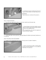
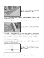
Using a modeling knife, cut a thin 1/4" long slot (per-
pendicular to the hinge line) through the aileron at the mark
you drew. Cut the slot about 1/4" behind the front of the
aileron so that the pivot point of the control horn will be over
the hinge line.
❑
Install one control horn using the same technique as with
the elevator and rudder control horns. Make sure the flat
side of the backplate is facing away from the aileron.
❑
Using a ruler and a pencil, measure out 1-1/2" from the inside edge of one aileron and draw a mark. This will be the
location of the control horn.
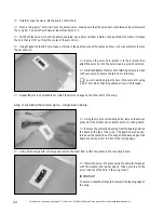
❑
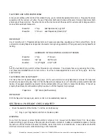
Plug the aileron servo lead into the proper slot in the receiver. Plug the ESC lead into the receiver and the flight
battery into the ESC . Turn on the radio system and center the servo using the trim lever on the transmitter.
❑
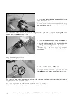
Thread one nylon clevis onto one 1.5mm x 150mm threaded pushrod wire. Thread the clevis on far enough to leave
room for adjustments later.

