


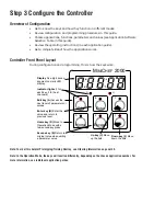


Introduction
Welcome to the M
INI
C
HEF
2000™
The M
INI
C
HEF
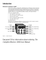
2000 is a configurable, time/temperature and machine function controller
that is preprogrammed for dozens of cooking applications. Its compact size and optional
horizontal/vertical orientation facilitates streamlined equipment design. It withstands
rigorous application environment conditions, with an 80ºC ambient rating and superior
EMI/RFI immunity. It is also backed by Watlow’s exclusive three-year warranty.
Each unit is equipped to offer:
•
two temperature sensor inputs
•
two event inputs (for machine control)
•
two heat control outputs
•
two event outputs (for machine control)
•
one audible alarm output
(See diagram below.)
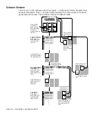
Depending on the application software you select, some or all of the inputs or outputs
are used. See the Application Selection Table that follows.
Figure 2 — Inputs and outputs.
See panel 23 for information about ordering
The
Complete M
INI
C
HEF
2000 User Manual.
A
B
D
E
C
F
G
H
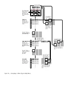
4 Inputs
Input 1
Thermocouple or RTD
Input 2
Thermocouple or RTD
Event Input 1
Event Input 2
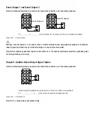
5 Outputs
Output 1
Switched DC or Solid-state Relay
Output 2
Switched DC or Solid-state Relay
Output 3
Event Output 1
Output 4
Event Output 2
Output 5
Audible Alarm Output
Содержание MINICHEF 2000
Страница 17: ...17 NOTES...
Страница 21: ...21 NOTES...


