Watlow Electric MINICHEF 2000 Скачать руководство пользователя страница 14

Step 3 Configure the Controller

Overview of Configuration 

•  Get to know the keys and how they function in different modes.

Review configuration and programming procedures in this guide. 

•  Choose applications, functions, parameters and values (see Application Software

Selection Table in this guide).

•  Review the operating instructions (in each application guide). 

•  Get a complete idea of how the application works. 

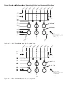
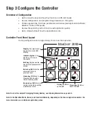
Controller Front Panel Layout

During configuration and programming, this is how the keys work:

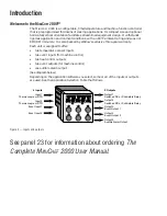
Note: To order this helpful Prototyping/Training Overlay, see Ordering Information on panel 23.

Note: In the Operation Mode, the keys will function differently, depending on the chosen application number. For

more information, see individual application guides.

A

B

D

E

G

H

Enter

Escape

Home

Edit

C

F

M

INI

C

HEF

 2000

Display Five-digit, seven-
segment numeric LED 
display.

Indicator lights (1 for 
each key, 2 for heat 
channels).

Edit key (A) Access the 
next level of parameters or 
values.

Enter key (B) Enter the 
value and return to 
previous level.

Home key (D) Move to 
Operation Mode with a 
two-second key press.

Escape key (E) Return to 
original value when editing 
a parameter value.

Up key (C) Move 
up the lists.

Down key (F) Move 
down the lists.

Содержание MINICHEF 2000

Страница 1: ...ols 1241 Bundy Blvd P O Box 5580 Winona Minnesota U S A 55987 5580 507 454 5300 Fax 507 452 4507 WMC2 XFSN 0008 June 1997 1116 Made in the U S A TOTAL CUSTOMER SATISFACTION Registered Company Winona M...

Страница 2: ...perature sensor inputs two event inputs for machine control two heat control outputs two event outputs for machine control one audible alarm output See diagram below Depending on the application softw...

Страница 3: ...ngle 1 Yes 1 or 2 2 1 Auto 17 Single 1 Yes 1 or 2 2 2 Auto 6 Single 1 No 1 or 2 2 3 Auto 20 Single 1 No 1 or 2 2 4 Manual N A Single 1 Yes No 1 or 2 5 Manual N A Single 1 No No 1 or 2 6 CONVECTION OVE...

Страница 4: ...nus for the chosen application To ease menu programming you may want to use the Prototyping Training Overlay available separately see Ordering Information on panel 23 5 Set menu security automatic men...

Страница 5: ...required for mating connectors Does not include wire bundle space require ments 4 13 in x 3 25 in x 2 00 in with collar mounted in horizontal position 3 25 in x 4 13 in x 2 00 in with collar mounted i...

Страница 6: ...m either pressed or welded Install the unit with either a horizontal or vertical mounting collar position Install mating connectors to unit Note This device should be used in systems that incorporate...

Страница 7: ...1 250 in 0 875 in 0 375 in 0 125 in 0 000 in 0 53 in 6 0 135 in 8 C L 1 8 7 5 i n 1 0 0 0 i n 0 5 0 0 i n 0 0 0 0 i n 0 5 0 0 i n 1 0 0 0 i n 1 8 7 5 i n 1 3 3 7 i n 1 3 3 8 i n 875 in ref 6 32 stud...

Страница 8: ...50 in 0 875 in 0 375 in 0 750 in 0 000 in 0 53 in 6 0 135 in 8 C L 1 0 0 0 i n 0 5 0 0 i n 0 0 0 0 i n 0 5 0 0 i n 1 0 0 0 i n 1 3 3 7 i n 1 3 3 8 i n 1 0 0 0 i n 1 0 0 0 i n 875 in ref 6 32 stud 4 mi...

Страница 9: ...24V ac Low Voltage WARNING To avoid potential electric shock use National Electric Code NEC safety practices when wiring and con necting this unit to a power source and to electrical sensors of perip...

Страница 10: ...ide for the application you are using Event Inputs 1 and 2 Note The following illustration is a view of the back of the controller not of the mating connector F 2 _ _ _ _ _ _ _ _ _ _ Figure 10c Switch...

Страница 11: ...or without RC Suppression F 2 _ _ _ 2 _ _ _ _ _ _ without RC Suppression F 2 _ _ _ 3 _ _ _ _ _ _ with RC Suppression Figure 11b Solid state Relay Option Note Not all software applications require Outp...

Страница 12: ...r without RC Suppression F 2 _ _ _ _ 2 _ _ _ _ _ without RC Suppression F 2 _ _ _ _ 3 _ _ _ _ _ with RC Suppression Figure 12b Solid state Relay Option Note Not all software applications require Outpu...

Страница 13: ...applications require event outputs 1 2 For specific information consult the application guide for the application you are using Output 5 Audible Alarm Output Signal Option Note The following illustra...

Страница 14: ...er this helpful Prototyping Training Overlay see Ordering Information on panel 23 Note In the Operation Mode the keys will function differently depending on the chosen application number For more info...

Страница 15: ...arrow key to scroll through the functions PARAMETERS Press the Up or Down arrow key to scroll through the parameters and their values VALUES Press the Up or Down arrow key to scroll through the range...

Страница 16: ...heir values VALUES Press the Up or Down arrow key to scroll through the range of values Press the Enter key to save the new value and return to the parameters Press the Enter key to return to the menu...

Страница 17: ...17 NOTES...

Страница 18: ...mber and appli cation number Much of this information is available on the controller case All of this information is also available via the MINICHEF 2000 main display by accessing the WatHelp Diagnost...

Страница 19: ...30mA maximum output minimum load resistance 150 non isolated Audible Output Options Switched dc signal 4 5V to 5 25V 30mA maximum output minimum load resistance 150 non isolated Internal audible alar...

Страница 20: ...signal non isolated Output Number 1 1 Switched dc 5V nominal 30mA non isolated 2 Solid state relay Form A 0 4A without RC suppression 3 Solid state relay Form A 0 4A with RC suppression Output Number...

Страница 21: ...21 NOTES...

Страница 22: ...ellnummer n F2 H oder U A oder C 1 2 3 oder 4 1 2 oder 3 1 2 oder 3 1 0 oder 1 0 oder 1 2 beliebige Buchstaben oder Zahlen Klassifikation Eingebautes elektronisches Temperaturregelsystem der Klasse II...

Страница 23: ...ellaneous Items DURA TECH Inc Custom Membrane Faceplates LaCrosse WI 608 781 2570 AMP Inc Prototyping EPROM Extraction Harrisburg PA Tool Part No 821980 1 1 800 522 6752 Pin Crimping Hand Tools Part N...

Отзывы: