


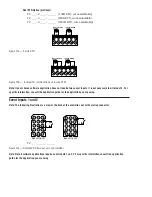

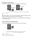


Event Output 1 and Event Output 2
Note: The following illustrations are views of the back of the controller, not of the mating connector.
F 2 _ _ - _ _ _ 1 - _ _ _ _ (switched dc, 5V nominal, 30mA, non-isolated outputs)
Figure 13a — Event Outputs.
ç
Warning: If event outputs 1 & 2 are used to cause or initiate machine motion, appropriate reasonable care should be
taken to prevent personal injury or machine damage as a result of machine motion.
Note: Not all software applications require event outputs 1 & 2. For specific information consult the application guide
for the application you are using.
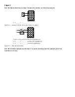
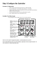
Output 5: Audible Alarm Output Signal Option
Note: The following illustrations are views of the back of the controller, not of the mating connector.
Alarm signal available at connector, 5V nominal, 30ma, non-isolated.
F 2 _ _ - _ _ _ _ - _ 0 _ _ (unit without internal audible alarm)
Figure 13c — Switched DC.
Note: Pin 5 is shared with event output 2 wiring.
1
2
3
4
5
6
7
8
9
5
9
10
11
12
13
14
15
Ext. Load
1
4
5
6
7
8
9
10
11
12
13
14
15
Ext. Load
3
2
Event Output 2
5
6
1
4
5
6
7
8
9
10
11
12
13
14
15
Ext. Load
3
2
Event Output 1
3
2
Содержание MINICHEF 2000
Страница 17: ...17 NOTES...
Страница 21: ...21 NOTES...


