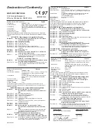
background image

Specifications 

(1032) 

Control Mode
• Single and dual heat channels, PID or on/off.

1

• Microprocessor-based, programmable, reverse-acting 

control outputs.

• User-selectable embedded application software defines

operation of display, keys, inputs, outputs, timing
action.

• One-step auto-tuning, WatHelp diagnostics, WatCurve

temperature compensation.

Agency
• CE approved:

89/336/EEC Electromagnetic Compatibility Directive
-EN 50081-1: Emissions
-EN 50082-1: Immunity
73/23/EEC Low-Voltage Directive
-EN 60730-1 and EN 60730-2-9: Safety

• NSF Listed, Criteria 2.

5

• AGA: UL tested to AGA standard Z21.23, UL File

#E43684.

• UL and C-UL recognized, UL 197, 873, 991 and CSA

standard C22.2-24, File # E43684.
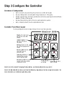
Operator Interface
• Membrane overlay, contamination and water resistant,

(supplied by customer).

• LED display, 5-digit, 0.56 in high, red.
• Displays times, temperatures, user prompts and 

diagnostic codes.

•  User-selectable time and temperature display formats.
• Temperature display formats—˚F or ˚C.
• Time display formats—H:MM:SS, HH:MM, or MMM:SS.
•  8 discrete indicator LEDs, red.
• 6 tactile feedback keys.
• Menu-driven operation and manual modes available.
• WatHelp diagnostics.
• Real-time clock option displays time of day.

Accuracy
• Calibration accuracy and sensor conformity

2

: ± 2.0°F 

for Type J thermocouple and RTD, ± 0.35% of span for 
Type K and E thermocouples, ±1 LSD, 77°F ± 5°F 
ambient and rated line voltage of ±10%.

• Accuracy span: 1000°F (540°C) minimum.
• Temperature stability: ± 0.15˚F/ ˚F (0.15˚C/˚C) change 

in ambient typical.

Sensors / Inputs
• Contact inputs, TTL compatible with internal pull-up 

resistor, two available.

• Thermocouple,

3

software selectable Type J, K or E, 

32 to 1200°F. (Dual-channel applications require at
least one ungrounded thermocouple).

• RTD,

3

2- or 3-wire, platinum, 100, 500, 1000

, at 0°C, 

software selectable DIN or JIS curves, 0 to 1200°F 
(3-wire will function as 2-wire).

• Input A / D resolution: 15 bit.
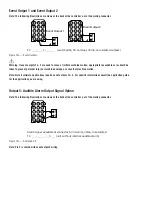
Output Options
• Solid-state relay, 0.4A, with or without contact suppres-

sion.

• Switched dc signal, 4.5V to 5.25V, 30mA maximum 

output, minimum load resistance > 150

, non-isolated.

Audible Output Options
• Switched dc signal, 4.5V to 5.25V, 30mA maximum 

output, minimum load resistance > 150

, non-isolated.

• Internal audible alarm, 75dB at 10 cm.
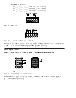
Connectors
• Sensor Input Terminal Strip

4

: RIACON, 6-position, 

quick-connect.

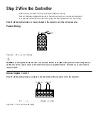
• Power Supply & Input / Output Terminal

4

: AMP, 

15-position, quick-connect.

Power / Line Voltage
• 20.4 to 26.4V

Å

(ac), 47 to 63Hz.

• 15VA maximum.
• For CE applications, input power must be limited to 

15W external to the control.

• Program retention upon power failure via non-volatile

memory.

• Battery / real-time clock option: 6-year lithium battery, 

provides power backup upon power failure, operation 
resumption after power recovery, ability to display time 
of day.

Operating Environment
• 32 to 176°F (0 to 80°C), 0 to 90% RH, non-condensing.

Storage Temperature
• -40 to 176°F (-40 to 80°C).
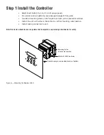
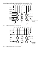
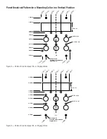
Mechanical
• Case: polycarbonate Lexan with adjustable mounting 

collar (vertical or horizontal orientation), designed for 
mounting on 16-, 18-, 20- and 22-gauge panels.

• Internal panel mounting requires a specified panel

cutout and four #6-32 studs or equivalent.

• Overall width x height x depth: horizontal - 4.13 in x 

3.25 in x 2.00 in; vertical - 3.25 in x 4.13 in x 2.00 in 
(Assumes mating connectors are attached. Does not 
include wire bundle space requirements.).

• Vibration: 2g, 10 to 150Hz, applied in any one of three

axes.

• Weight: 6.50oz maximum.

Program Storage
• All non-embedded user and factory programs are 

stored in non-volatile memory. Can be changed by 
reprogramming.

Sample/Update Rates
• 1 input: 4Hz.
• 2 inputs: 4Hz.
• PID: 1Hz.
• Control outputs: 100Hz.
• Display: 10Hz.

1

The M

INI

C

HEF

2000 controller is to be used in systems with an 

external high temperature limiting device.

2

Thermocouple lead resistance of 200

causes < 1°C error. RTD, 22

gauge wire will not contribute more than 0.086°F error / ft.

3

Dual channel applications require either two thermocouple sen-

sors or two identical RTD sensor types.

4

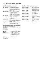
For mating connector information, see Ordering Information 

Accessory section.

5

Certified for thermometer accuracy (oven and hot food holding 

applications from 32°F to 60°F) when used with RTD or type J

thermocouple probes.

Содержание MINICHEF 2000

Страница 1: ...ols 1241 Bundy Blvd P O Box 5580 Winona Minnesota U S A 55987 5580 507 454 5300 Fax 507 452 4507 WMC2 XFSN 0008 June 1997 1116 Made in the U S A TOTAL CUSTOMER SATISFACTION Registered Company Winona M...

Страница 2: ...perature sensor inputs two event inputs for machine control two heat control outputs two event outputs for machine control one audible alarm output See diagram below Depending on the application softw...

Страница 3: ...ngle 1 Yes 1 or 2 2 1 Auto 17 Single 1 Yes 1 or 2 2 2 Auto 6 Single 1 No 1 or 2 2 3 Auto 20 Single 1 No 1 or 2 2 4 Manual N A Single 1 Yes No 1 or 2 5 Manual N A Single 1 No No 1 or 2 6 CONVECTION OVE...

Страница 4: ...nus for the chosen application To ease menu programming you may want to use the Prototyping Training Overlay available separately see Ordering Information on panel 23 5 Set menu security automatic men...

Страница 5: ...required for mating connectors Does not include wire bundle space require ments 4 13 in x 3 25 in x 2 00 in with collar mounted in horizontal position 3 25 in x 4 13 in x 2 00 in with collar mounted i...

Страница 6: ...m either pressed or welded Install the unit with either a horizontal or vertical mounting collar position Install mating connectors to unit Note This device should be used in systems that incorporate...

Страница 7: ...1 250 in 0 875 in 0 375 in 0 125 in 0 000 in 0 53 in 6 0 135 in 8 C L 1 8 7 5 i n 1 0 0 0 i n 0 5 0 0 i n 0 0 0 0 i n 0 5 0 0 i n 1 0 0 0 i n 1 8 7 5 i n 1 3 3 7 i n 1 3 3 8 i n 875 in ref 6 32 stud...

Страница 8: ...50 in 0 875 in 0 375 in 0 750 in 0 000 in 0 53 in 6 0 135 in 8 C L 1 0 0 0 i n 0 5 0 0 i n 0 0 0 0 i n 0 5 0 0 i n 1 0 0 0 i n 1 3 3 7 i n 1 3 3 8 i n 1 0 0 0 i n 1 0 0 0 i n 875 in ref 6 32 stud 4 mi...

Страница 9: ...24V ac Low Voltage WARNING To avoid potential electric shock use National Electric Code NEC safety practices when wiring and con necting this unit to a power source and to electrical sensors of perip...

Страница 10: ...ide for the application you are using Event Inputs 1 and 2 Note The following illustration is a view of the back of the controller not of the mating connector F 2 _ _ _ _ _ _ _ _ _ _ Figure 10c Switch...

Страница 11: ...or without RC Suppression F 2 _ _ _ 2 _ _ _ _ _ _ without RC Suppression F 2 _ _ _ 3 _ _ _ _ _ _ with RC Suppression Figure 11b Solid state Relay Option Note Not all software applications require Outp...

Страница 12: ...r without RC Suppression F 2 _ _ _ _ 2 _ _ _ _ _ without RC Suppression F 2 _ _ _ _ 3 _ _ _ _ _ with RC Suppression Figure 12b Solid state Relay Option Note Not all software applications require Outpu...

Страница 13: ...applications require event outputs 1 2 For specific information consult the application guide for the application you are using Output 5 Audible Alarm Output Signal Option Note The following illustra...

Страница 14: ...er this helpful Prototyping Training Overlay see Ordering Information on panel 23 Note In the Operation Mode the keys will function differently depending on the chosen application number For more info...

Страница 15: ...arrow key to scroll through the functions PARAMETERS Press the Up or Down arrow key to scroll through the parameters and their values VALUES Press the Up or Down arrow key to scroll through the range...

Страница 16: ...heir values VALUES Press the Up or Down arrow key to scroll through the range of values Press the Enter key to save the new value and return to the parameters Press the Enter key to return to the menu...

Страница 17: ...17 NOTES...

Страница 18: ...mber and appli cation number Much of this information is available on the controller case All of this information is also available via the MINICHEF 2000 main display by accessing the WatHelp Diagnost...

Страница 19: ...30mA maximum output minimum load resistance 150 non isolated Audible Output Options Switched dc signal 4 5V to 5 25V 30mA maximum output minimum load resistance 150 non isolated Internal audible alar...

Страница 20: ...signal non isolated Output Number 1 1 Switched dc 5V nominal 30mA non isolated 2 Solid state relay Form A 0 4A without RC suppression 3 Solid state relay Form A 0 4A with RC suppression Output Number...

Страница 21: ...21 NOTES...

Страница 22: ...ellnummer n F2 H oder U A oder C 1 2 3 oder 4 1 2 oder 3 1 2 oder 3 1 0 oder 1 0 oder 1 2 beliebige Buchstaben oder Zahlen Klassifikation Eingebautes elektronisches Temperaturregelsystem der Klasse II...

Страница 23: ...ellaneous Items DURA TECH Inc Custom Membrane Faceplates LaCrosse WI 608 781 2570 AMP Inc Prototyping EPROM Extraction Harrisburg PA Tool Part No 821980 1 1 800 522 6752 Pin Crimping Hand Tools Part N...

Отзывы: