Waterous Y Series Скачать руководство пользователя страница 10

F-1031,  Section  4307

Page 9 of 12

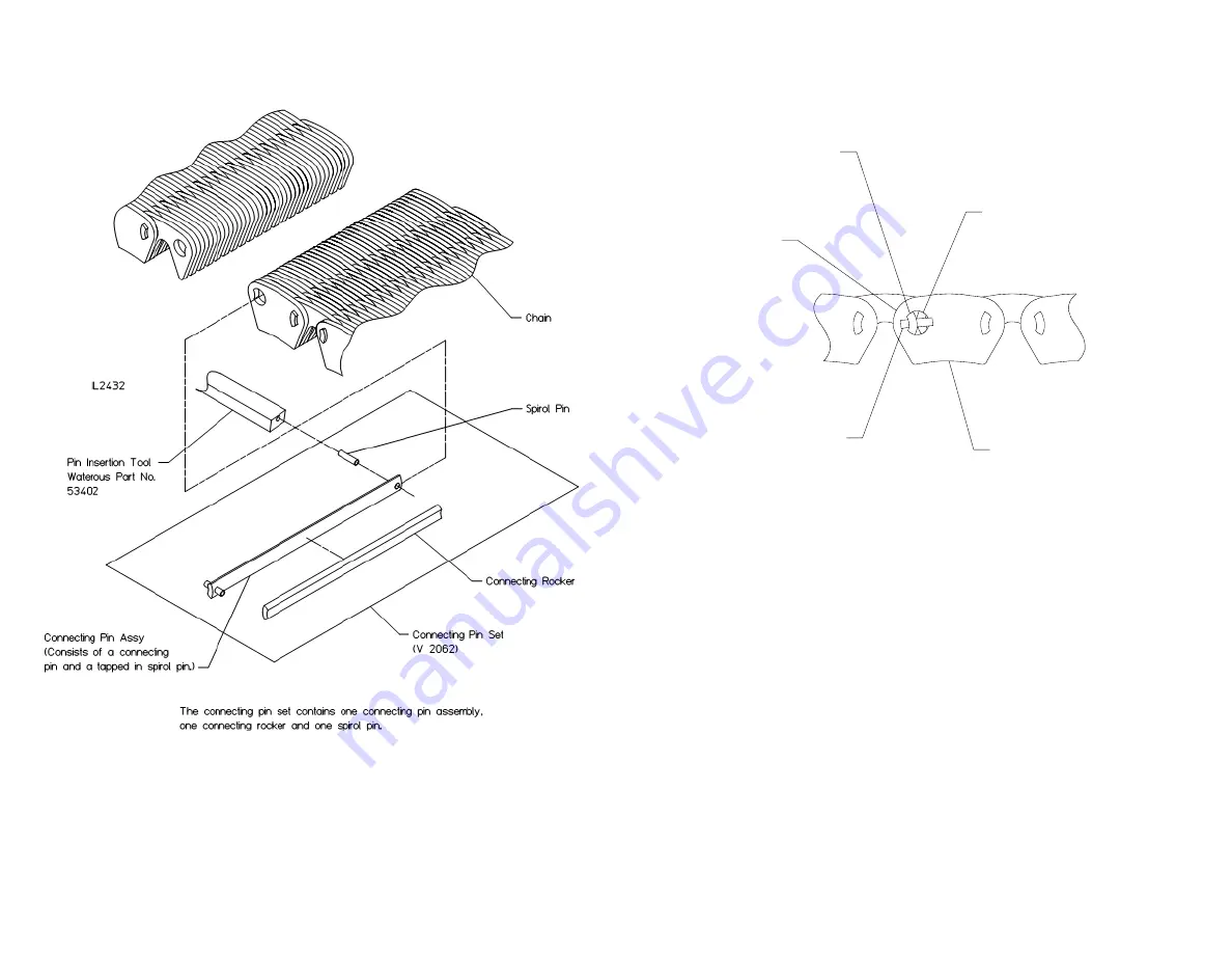
Figure 8. Connecting Pin Set

Figure 9. Connecting Pin Orientation

Spirol Pin

Connecting Rocker

Guide Link

Joining End of Chain

Connecting Pin Assembly

(Spirol pin on opposite

side must be tapped in to

complete installation.)

IL2433

Содержание Y Series

Страница 1: ...ssembly of Coupling Shaft Assembly 4 Disassembly of Drive Shaft Assembly 4 Miscellaneous 4 Inspection and Repair 4 Reassembly 5 Guidelines for Installing Ball Bearings Oil Seals and O rings 5 Cap and...

Страница 2: ...it is separately mounted and would interfere with removal of the transmission As various types of priming pumps are available see separate instructions covering the type furnished with the transmissi...

Страница 3: ...ide to side on the housing 6 Remove cap screws T52 bolts T93 nuts T69 and lock washers T53 attaching bottom section to mid section Drive dowels T131 from bottom section Separate bottom section and mid...

Страница 4: ...moved 18 Removal of cap from mid section only required if either component needs to be replaced Note that removal will make it easier to handle the assembly during driven shaft removal and reassembly...

Страница 5: ...T4 from teeth on drive shaft T13 2 Remove housing T11 from bearing T15 and press oil seal T45 from housing T11 Discard oil seal 3 With suitable puller remove tachometer gear T10 and sleeve T14 4 This...

Страница 6: ...ap with or without midsection into a press with the oil pump support housing T31 resting on the press base Ensure housing and cap are properly supported Position spacer T29 and driven sprocket T26 ins...

Страница 7: ...n coupling shaft 3 Slip spacer T2 over shaft T44 and seat it against bearing T1 or T15 4 Press on outer bearing T1 before 4 25 93 T184 1 04 94 to 4 01 95 or T15 after 4 25 95 tight against spacer T2 5...

Страница 8: ...k until the shaft opening is lined up with the opening in the sector gear T47 or sector gear shift lever 9 Install shift arm spring housing T59 and shift arm spring T61 10 Install shift arm T62 on shi...

Страница 9: ...lf way between the drive sprocket and driven sprocket see chart below for maximum deflection Replace chain if deflection is greater than those displayed in the chart below 6 Loosen drive shaft housing...

Страница 10: ...12 Figure 8 Connecting Pin Set Figure 9 Connecting Pin Orientation Spirol Pin Connecting Rocker Guide Link Joining End of Chain Connecting Pin Assembly Spirol pin on opposite side must be tapped in to...

Страница 11: ...etainers in place until an appropriate cover or shift unit is installed Installing the Coupling Shaft and Housing Assembly to the Case NOTE The drive line assembly was factory shimmed to limit the axi...

Страница 12: ...7 5 Install plug T98 a pressure gauge may have been installed in tee T102 and case T28 Reassembly of Accessories to the Transmission Electric Shift Assembly 1 Make sure adjusting screws T86 are in pla...

Страница 13: ...tellated lock nut with a self locking nut T43 and torque to 475 525 ft lbs 3 Repeat same installation procedure at coupling shaft end unless compan ion flange was previously installed at the time the...

Страница 14: ......

Отзывы: