background image

11

to the Dispensing Faucet. Route to the tubing 
to the Drain Clamp and trim to length. 


NOTE:

 When cutting the polytubing make  

clean, square cuts, failing to do so could 
result in poor con nec tions and possible leaks. 


CAUTION:

 The lowest point of the line 

should be the point of connection to the Drain 
Clamp. There should be no sag in the line as 
this may cause ex ces sive noise as the reject 
water is fl owing to drain.

•Refer to Fig. 4, page 12. Insert the tubing 

into the Drain Clamp. Make sure the 
tubing is pressed all the way in to create a 
pressure tight connection.

NOTE: If you want to pull the tubing out for 

some reason, push the ring around the 
tubing in and pull the tubing out.

D.   R.O. Manifold Assembly Installation 

     Locate the site per Sec. III, C.3,  page 7. Various 

in stal la tion sites will require different types 
of mount ing fasteners; be sure the fastener 
selected will provide a fi rm, solid mounting. 
A support panel may be necessary on thin 
cabinet walls or to span between wall studs on 
par ti cle board or drywall. 

     Do not drill through exterior cabinet walls or 

leave sharp wood screw points exposed in 
readily accessible cabinet interiors. 

    The close proximity of a dishwasher or a trash 

compactor may require spe cial fabrication of a 
mounting plate. 

1.   The mounting bracket will accept either #10 

or #12 (5mm) mounting screws spaced on 
6" (15 cm) centers. Allow at least 4" (10 cm) 
of clearance beneath the fi lter housings to 
accommodate fi lter changes. Mark the two 
locations (the bracket can be used as a 
template). Install the screws and tighten them 
until the heads are about 

5

/

8

" from the wall.

2.  Locate the ¼" Red Feed Water Tubing. 

Remove the red plug from the fi tting labelled 
“In” on the manifold and insert the tubing. 
Reference the special supplement sheet in 
the carton for proper connection of all tubing 
and removal of plugs. Run the tubing along 
its course to the Feed Water Saddle Valve, 
trim to length. (Refer to Fig. 1, page 5.) 

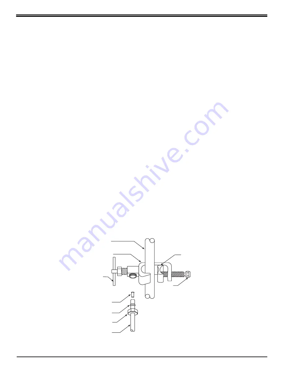
     Refer to Fig. 3,. To the end of the red 

polytube install the Compression Nut, the  
Plastic Ferrule, and the Insert. Connect to the 
Feed Water Saddle Valve.

3.  Locate the ¼" Black Drain Tubing connected 

to the Dispensing Faucet. Remove the black 
plug from the fi tting labelled “Drain” on the 
manifold and insert the tubing. The end of the 
Black Drain Tubing that should be inserted 
into the “Drain” port will have a blue drain 
restrictor in it. If tubing needs to be trimmed 

Cold Water

Line

Saddle

Valve

Handle

Insert

Plastic

Ferrule

Red Tubing To

Manifold

Inlet

Compression

Nut

Tightening

Screw

Reversible
Back Plate

FEED WATER SADDLE VALVE 

Figure 3

Содержание ECLIPSE WRO-35

Страница 1: ...58 for the reduction of the claims specified on the Performance Data Sheet E C L I P S E Reverse Osmosis Drinking Water System from Water Right Sold and serviced by authorized Water Right dealers Ins...

Страница 2: ...infection with Cryptosporidium from drinking water This guidance pertains to people with HIV AIDS patients receiving treatment for cancer recipients of organ or bone marrow transplants transplant pati...

Страница 3: ...the feed water supply to prevent excess reject water from going to drain when the unit is not producing water WATER QUALITY MONITOR The Water Quality Monitor has been integrated into the faucet base...

Страница 4: ...n figures are for a new Membrane that has been rinsed for 24 hours The production rate of a new Membrane can decrease by 10 per year or more depending upon the scaling and fouling tendencies of the Fe...

Страница 5: ...ation may include wood screws or machine screws and nuts for mounting the manifold or concrete anchors for hanging on basement wall Additional tubing or tube connectors Plastic wire ties for organizin...

Страница 6: ...ADDLE VALVE COLD WATER LINE ONLY 1 AIR GAP REQUIRED MOUNT HOLDING TANK ON SHELF OR STRAP BETWEEN FLOOR JOISTS Shelf Or Straps Not Included FLOOR BASEMENT FLOOR NOTE FOR REFRIGERATOR WATER DISPENSER OR...

Страница 7: ...illing of water pitchers and glasses and an open area beneath the faucet under the sink for attaching product and drain tubing are considerations A 2 diameter flat surface is required above and below...

Страница 8: ...chipping Drill a pilot hole for the porcelain cutter Use the pilot drill supplied with the kit or a carbide tipped drill When drilling the 1 hole drill slowly and carefully the porcelain chips easily...

Страница 9: ...ain Tubing Allow space for thickness of Mounting Surface and Slotted Washer Plastic Spacer Spout Plastic Shipping Plug Remove 7 16 Stud Mounting Surface 1 drill hole 7 16 Washer 7 16 Hex Nut 3 8 Polyt...

Страница 10: ...e Feed Water Saddle Valve on the tubing for 3 8 OD tubing use the back plate side with the small groove to prevent distortion of the tubing for larger tubing up to 5 8 OD use the large groove of the b...

Страница 11: ...r a trash compactor may require special fabrication of a mounting plate 1 The mounting bracket will accept either 10 or 12 5mm mounting screws spaced on 6 15 cm centers Allow at least 4 10 cm of clear...

Страница 12: ...Blue Polytube where it would be convenient to install and change the In Line Filter Make a clean straight cut to insure proper connections The Out port on the In Line Filter should be towards the fau...

Страница 13: ...t 8 hours before emptying each tank When the Faucet is first opened expect air and carbon fines very fine black powder from the In Line and Activated Carbon Post Filters to be rinsed out This is norma...

Страница 14: ...olding Tank to the Tee see Fig 1 page 5 Put 50 drops of bleach this is tsp or 3 ml into the tubing and reconnect it to the Tee NOTE Now is the convenient time to change the In Line Activated Carbon Po...

Страница 15: ...es 2 5 oz 2 min 1 25 oz min 1 25 oz min x 11 2 14 gpd The Reject Ratio is the amount of water produced compared to the amount of water flowing to drain Reject Ratio Reject Rate_ Product Rate EXAMPLE T...

Страница 16: ...m of TDS would exert a backward pressure of about 15 psig on the membrane Net Pressure Differential Feed Water Pressure Holding Tank Pressure Osmotic Pressure The higher the net pressure differential...

Страница 17: ...101 4 31 9 120 7 37 0 140 0 42 1 159 3 47 2 178 7 500 14 3 54 1 19 4 73 4 24 5 92 7 29 6 112 0 34 7 131 3 39 8 150 6 44 9 169 9 1000 11 7 44 3 16 9 64 0 22 0 83 3 27 1 102 6 32 2 121 9 37 3 141 2 42...

Страница 18: ...f Membrane life is unusually short find and correct the problem Replace Membrane Feed Water Saddle Valve is plugged or closed Clogged Sediment Carbon Module or Activated Carbon Module Low water pressu...

Страница 19: ...ion Tastes and odors in the Product Water The Product Water and Drain Water lines are reversed No drain flow Drain Restrictor is clogged No drain flow the drain orifice in the Air Gap Faucet is plugge...

Страница 20: ...20 NOTES...

Страница 21: ...21 MADE IN USA EXPLODED VIEW PARTS LIST 1 2 3 4 5 6 7 8 9 10 11 12 13 14 17 19 18 15 16 21 Nitrate Nitrite Test Kit...

Страница 22: ...in Restrictor 80 GPD 303 lpd Blue 17 S7125X Activated Carbon Module 18 S1405 1 4 3 8 Fitting Wrench 19 S3072 Wrench for Housing 20 S7206W In Line Activated Carbon Post Filter 21 S1447 Nitrate Nitrite...

Страница 23: ......

Страница 24: ...also pay for shipping or travel charges to return the defective part s What Does This Warranty Not Cover This warranty does not cover the disposable sediment and carbon filters whose service life dep...

Отзывы: