5
SECTION III. PREPARATION
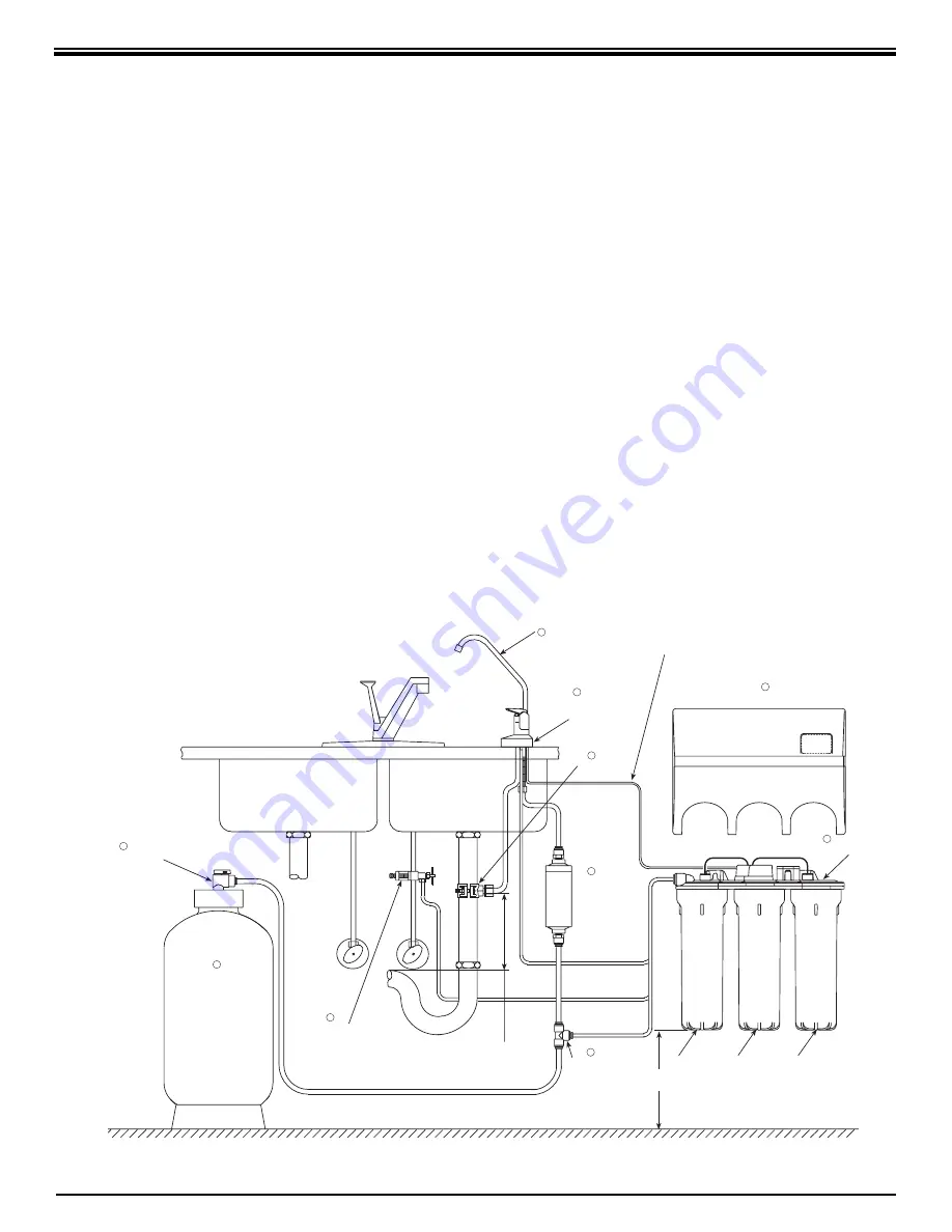
A. Major System Components
The following components comprise the R.O.
Drinking Water System. (Refer to Fig. 1, below
for general system layout.)
• An R.O. Manifold assembly.
• Housings and Housing O–rings.
• A Drinking Water Holding Tank.
• A Dispensing Faucet with Water Quality
Monitor Assembly.
• A Feed Water Saddle Valve.
• A Drain Clamp.
• Plastic Tubing and tube connectors.
• A Reverse Osmosis Mem brane sealed in a
plastic bag.
• A Sediment/Carbon Module, shrink wrapped.
• An Activated Carbon Module, shrink
wrapped.
• An In–Line Activated Carbon Post Filter,
shrink wrapped.
• Other items necessary for installation may
include wood screws or machine screws and
nuts for mounting the manifold, or concrete
anchors for hanging on basement wall.
Additional tubing or tube connectors. Plastic
wire ties for organizing tubing.
TYPICAL WRO-35 UNDER SINK INSTALLATION DIAGRAM
Figure 1
DISPENSING
FAUCET WITH
AIR GAP
1
DRAIN
(1/4" Black)
COVER
IN-LINE
ACTIVATED
CARBON
POST FILTER
DRAIN
(3/8" Black)
PRODUCT
(3/8" Blue)
INLET
(1/4" Red)
ACTIVATED
CARBON
MODULE
REVERSE
OSMOSIS
MEMBRANE
HOUSING
(1/4" Yellow)
SEDIMENT/
CARBON
MODULE
SADDLE VALVE
(COLD WATER LINE ONLY)
RO MANIFOLD
DRAIN
CLAMP
HOLDING TANK
SHUTOFF VALVE
(Open Position)
DRINKING
WATER
HOLDING
TANK
LOCATE DRAIN CLAMP ABOVE
"P" TRAP
TANK
(3/8" Yellow)
POLYTUBE
TEE
NITRATE/NITRITE
TEST KIT
11
10
9
7
6
5
4
3
2
8
4" MIN.
WATER QUALITY
MONITOR
FAUCET BASE
WATER QUALITY
MONITOR CABLE
Содержание ECLIPSE WRO-35
Страница 20: ...20 NOTES...
Страница 23: ......


