12
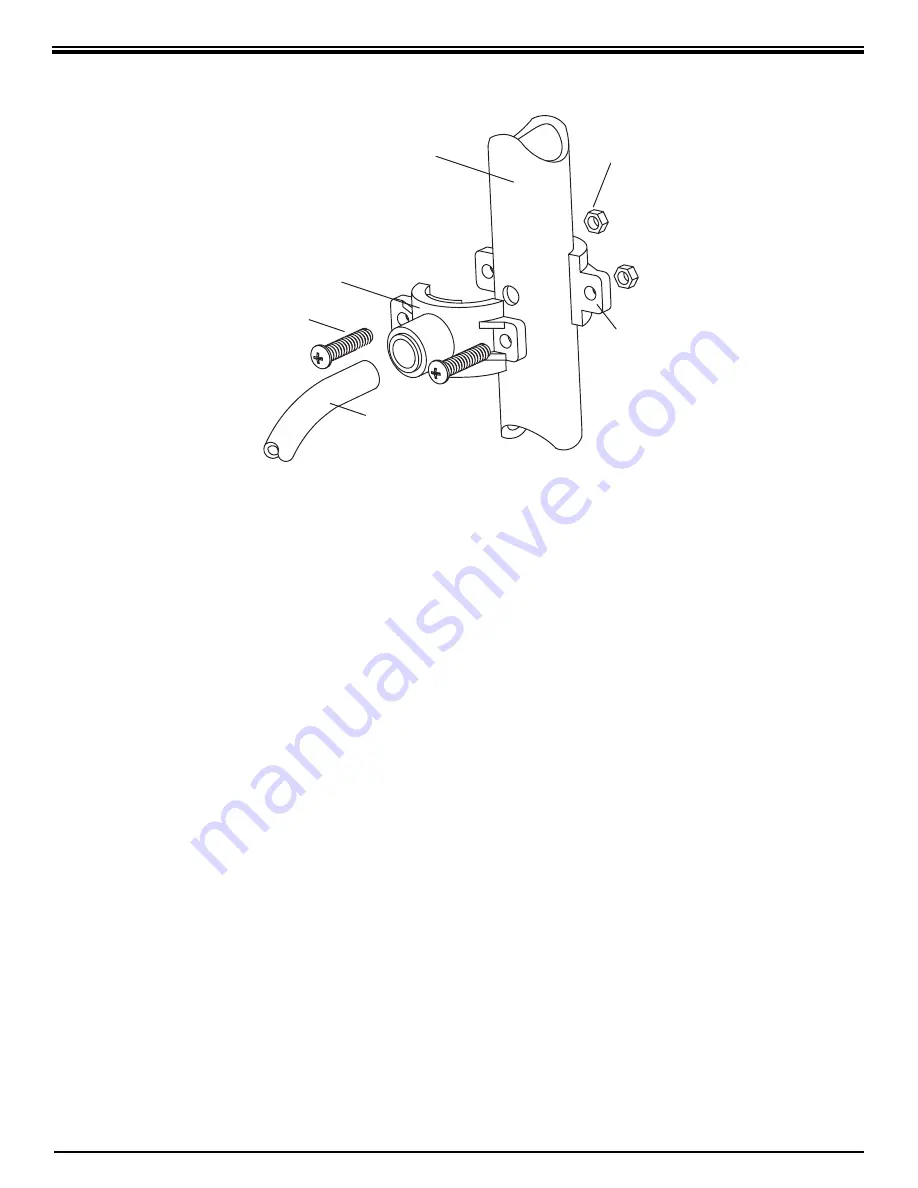
3/8" DRAIN CLAMP ASSEMBLY
to length, carefully slit ¼" Black Drain Tubing
end that has the blue drain restrictor in it
being careful not to damage the hose barb
on the drain restrictor. Remove restrictor from
tubing, make a square cut, and reinsert the
drain restrictor. Allow the tubing to relax, then
press drain restrictor fi rmly again to insure
proper seating.
4. Locate the ¼" yellow tubing with the tee
attached to one end. Remove the yellow plug
from the fi tting labelled "Out" on the manifold
and insert the tubing.
5. Locate the
3
/
8
" Blue Product Water Tubing
attached to the Dispensing Faucet. Firmly
press one end into the tee. (Refer to Fig.
1, page 5.) The fi ttings will grab the tubing
and seal it in place. Make sure the tub ing is
pressed all the way in to create a pressure
tight connection.
NOTE:
If you want to pull the tubing out
for some reason, push the ring around the
tubing in and pull the tubing out.
6. Hang the Manifold Assembly on the
mounting screws and tighten. DO NOT
OVERTIGHTEN.
7. Remove the wrap
ping from the
In–Line Activated Carbon Post Filter. Slice
the
3
/
8
" Blue Polytube where it would be
convenient to install and change the In–Line
Fil ter. Make a clean straight cut to insure
proper connections. The “Out” port on the
In–Line Filter should be towards the faucet.
Firmly press in the tubing. The fi ttings will
grab the tubing and hold and seal it in place.
Make sure the tubing is pressed all the way
in to create a pressure tight connection.
E. Position the Drinking Water Hold ing Tank and
Make the Final Hose Connections.
1. Check the tank precharge pressure. Make
sure it is between 5 to 7 psig. If not, use a
bicycle hand pump or other pump to bring the
pressure up to the 5 to 7 psig range.
2. Pull the cap/plug off the top of the tank where
the Tank Shut–Off should go. (Refer to Fig. 1,
page 5.)
3. Wrap the white Tefl on tape, included in the
box, three times around the ¼" male outlet
thread. Wrap in the direction of the threads
(clockwise when looking down on the Holding
Tank). The tape will act as a thread sealant.
Screw on the Holding Tank Shut–Off Valve.
4. Locate the
3
/
8
" Yellow Tubing. Firmly press
one end into the Holding Tank Shut–Off Valve
and the other end into the tee. (Refer to Fig.
1, page 5.) The fi ttings will grab the tubing
Figure 4
Drain Clamp
Front Plate
Drain Pipe
1/4" Nut
1/4" Screw
Drain Clamp
Back Plate
Black Drain Tubing
Содержание ECLIPSE WRO-35
Страница 20: ...20 NOTES...
Страница 23: ......


