Wärtsilä JOVYSTAR HP 200-800kVA BAX 4640 E
- 26 -
4.4
Electrical Connections
ATTENTION:
Even with switched off mains there is a dangerous high battery voltage inside the UPS. All installations
and connections may only be carried out by qualified technicians. The technician must familiarize himself
with the special features of this UPS by carefully reading and understanding this manual.
Please observe the special notices for connections of a parallel-system.
The work for electrical connection is a part of an electrician who installs the whole electric installation. It is not part of the
UPS manufacturer. For this reason, the following recommendations are only an indication, as the UPS manufacturer is
not responsible for the electrical installation.
In any case we recommend carrying out the installation and the electrical connections to the UPS in accordance to the
local rules and standards.
During the electrical installation make sure a right phase rotation at the three-phase input terminals of the UPS.
In case of strong electromagnetic fields emission it is recommended to use a shielded cable between UPS and the load.
In accordance to EN 62040-1 a mains-feed-back protection has to be provided for the UPS, preventing a current flow
from the output of the UPS back into mains at a single fault of the system. Therefore both the lines for the main input and
the bypass lines have to be fed via a contactor, which opens in case of a mains blackout.
For improving the quality of connection of the UPS flexible cables are recommended. A cable clamp must be provided by
the end-user directly at the structure of the frame or right below the UPS cabinet.
The wire diameters given in the below table refer to a distance of 20m between load and UPS. These values are recom-
mendations only. They have to be recalculated particularly considering the actual environment conditions!
At larger distances the permissible voltage drop, the environmental temperature and the cable grounding have to be
dimensioned according to VDE or local rules. Local rules for the protection ground-wires have to be considered.
The suitable diameters of cables and the sizes of the fuses are to be designed with regard to the environmental tempera-
ture, the cable grouping and length of cables according to the local rules and according to VDE.
The terminals are positioned at the lower part of the UPS and they can be accessed by opening the front door.
ATTENTION:
The input lines to the UPS must be fuse protected. The use of residual current switches in the line sup-
plying the UPS is not recommended. The leakage current due to the RFI filters is rather high and it can
cause spurious tripping of the protection device.
If any residual-current-switch has to be used, it is recommended the use of a device with short-time de-
lay for differential currents higher than 300mA.
The following table represents a summary about the current carrying capacity acc. DIN VDE- and EN-rules at an envi-
ronmental temperature of 30°C. The necessary diameters of cable and the sizes of the fuses are to be designed with
regard to the environmental temperature, the cable grouping and length of cables according to the local rules and ac-
cording to VDE.
NOTE:
The suitable cable cross-sections and sizes of the fuses must be determined considering the ambient
temperature, the cable grouping and the cable lengths according to the local rules and the local regula-
tions of the electrician or planner. Since the manufacturer of the installation does not know the local
factors, a liability of the manufacturer is impossible concerning the electrical installation.
The given values of cable diameters do not reflect the required diameters of the protective earth cable! They
have to be calculated in accordance to VDE 0100 part 540 or an applicable local rule.
UPS size
200kVA
250kVA
300kVA
Input fuses [A
gL
]
Rectifier
3 x 315
3 x 400
3 x 500
Bypass
3 x 315
3 x 400
3 x 500
Input cables (mm²)
Rectifier
3 x 185
3 x 240
3 x 2 x 150
Bypass
4 x 185
4 x 240
4 x 2 x 150
Output cables (mm²)
4 x 185
4 x 240
4 x 240
Battery cables (mm²)
2 x 240
2 x 240
2 x 2 x 185
External battery cabinet, circuit breaker / fuses [A
gL
]*
2 x 400
2 x 400
2 x 500
* applicable for DC-applications
i
Содержание JOVYSTAR HP 200 kVA
Страница 1: ...Operating manual W rtsil JOVYSTAR HP 200 800kVA BAX 4640 E...
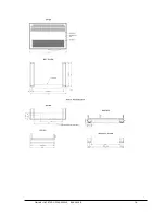
Страница 17: ...W rtsil JOVYSTAR HP 200 800kVA BAX 4640 E 17 4 3 1 Dimensions W rtsil JOVYSTAR HP E 200 300 kVA...
Страница 18: ...W rtsil JOVYSTAR HP 200 800kVA BAX 4640 E 18...
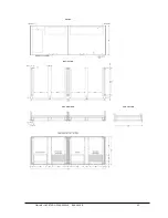
Страница 19: ...W rtsil JOVYSTAR HP 200 800kVA BAX 4640 E 19 4 3 2 Dimensions W rtsil JOVYSTAR HP E 400 kVA...
Страница 20: ...W rtsil JOVYSTAR HP 200 800kVA BAX 4640 E 20...
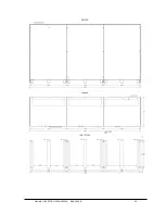
Страница 21: ...W rtsil JOVYSTAR HP 200 800kVA BAX 4640 E 21 4 3 3 Dimensions W rtsil JOVYSTAR HP E 500 600 kVA...
Страница 22: ...W rtsil JOVYSTAR HP 200 800kVA BAX 4640 E 22...
Страница 23: ...W rtsil JOVYSTAR HP 200 800kVA BAX 4640 E 23 4 3 4 Dimensions W rtsil JOVYSTAR HP E 800 kVA...
Страница 24: ...W rtsil JOVYSTAR HP 200 800kVA BAX 4640 E 24...
Страница 25: ...W rtsil JOVYSTAR HP 200 800kVA BAX 4640 E 25...
Страница 28: ...W rtsil JOVYSTAR HP 200 800kVA BAX 4640 E 28 Terminal board 400 kVA...
Страница 29: ...W rtsil JOVYSTAR HP 200 800kVA BAX 4640 E 29 Terminal board 500 800 kVA...
Страница 30: ...W rtsil JOVYSTAR HP 200 800kVA BAX 4640 E 30 4 4 2 Internal Connections between both switch cabinets...


