Warmhaus LAWA 18 Скачать руководство пользователя страница 8

8

warmhaus.com

2.2.9. Radiator and Domestic Hot Water Installations

Radiator and ground heating installation should be constructed in 
accordance with technical specifications and heat loss calculation. Radiator 
type and amount and ground heating installation pipe amount should 
comply with the heat loss calculation.
•  Radiator installation should be designed as resisting to at least 6 bars.
•  If the city grid pressure is higher than 6,5 bars, pressure reducer must be 

installed.

•  It is recommended to construct the radiator installation as double line 

and without using elbow and joints as much as possible.

•  Strainer filter must be installed in radiator return and tap water (city grid) 

input line.

•  For example; as the radiator cycle's 8 litres expansion (24 kW) tank can 

support maximum (80 °C'in radiator system) 140 litre and (55. °C in 
ground heating system) 170 litre installation water expansion, additional 
expansion tank should be used for larger installation volumes. 170 litre 
installation water expansion, additional expansion tank should be used 
for larger installation volumes.

•  If the room thermostat and thermostatic radiator valve will be used 

together; thermostatic valve should not be installed in radiators in the 
place where room thermostat is available.

•  Cross connection must be made for efficient functioning in radiators 

longer than 1,5 m.

•  Covers should be used for radiator and domestic hot water wall passages 

and fixed with wall clamps to prevent expansions due to heating.

•  Combi can function under minimum 0,5 bar domestic hot water pressure 

and that corresponds to a very low flow rate and therefore, it shall not 
possible to adjust the requested domestic hot water temperature. For 
this reason, domestic hot water line should be installed at shortest 
distance with pipe having at least ½” internal diameter and by using 
elbows as low as possible. At least 1 bar pressurized grid input water 
should be supplied to ensure adequate domestic hot water. Hydrophore 
should be used if required.
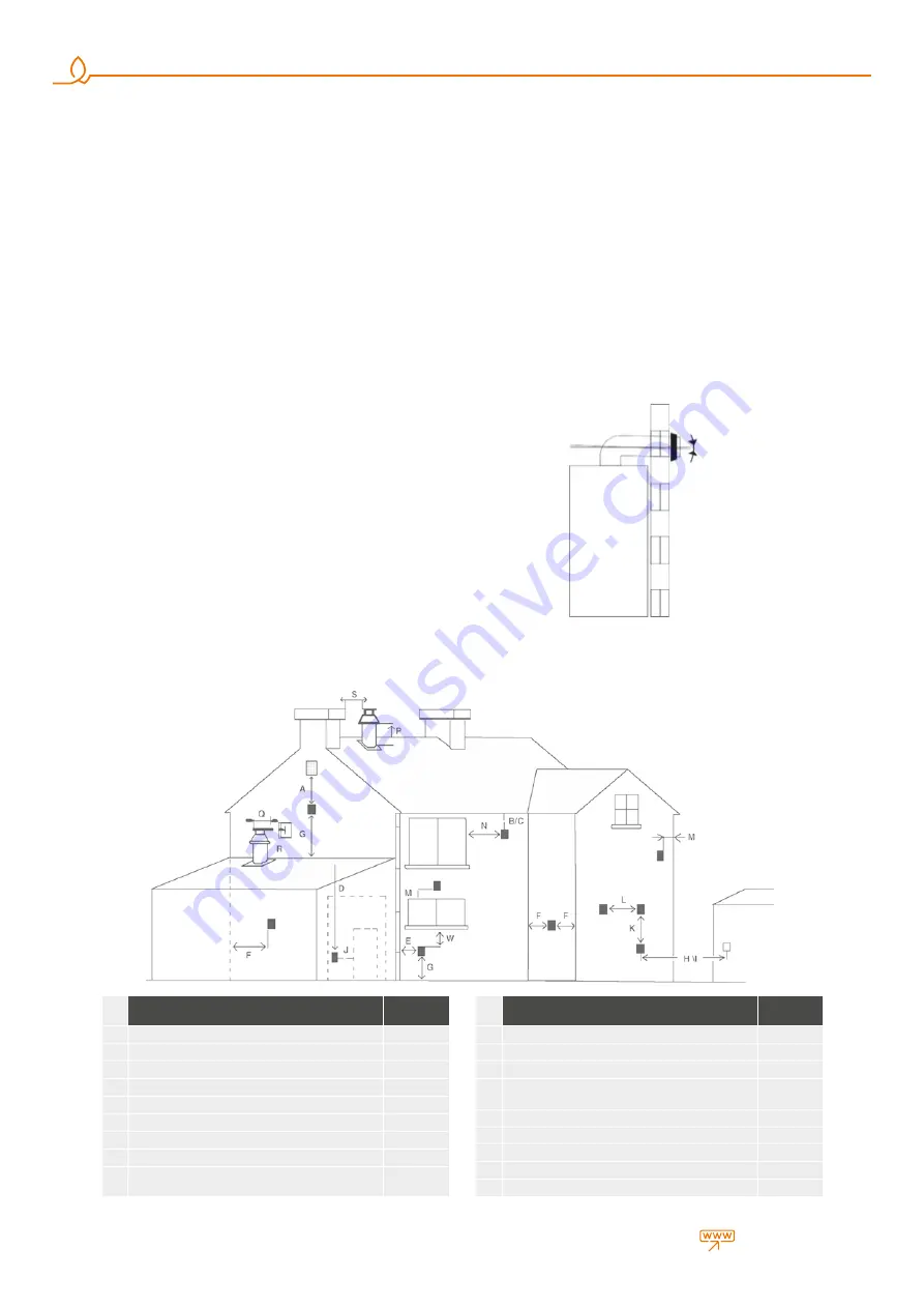
Figure 10 

Flue peripheral positions

Flue Position

Minimum 

Distance

A

Under a window

300 mm.

B

Under water groove

75 mm.

C

Under fringes

200 mm.

W

Under balconies

200 mm.

E

To vertical water discharge pipes

150 mm.

F

interior or exterior corners

300 mm.

G

At ground, roof or balcony level

300 mm.

H

On another wall corresponding to the flue

600 mm.

S

To another flue
To another wall than the garage wall

1200 mm.

Flue Position

Minimum 

Distance

J

To another wall than the garage wall

1200 mm.

R

To another flue than the same wall (vertical)

1500 mm.

Q

To another flue than the same wall (vertical)

300 mm.

M

On another window/culvert
On another window /culvert vertically

300 mm.

P

On the roof level

300 mm.

F

To an adjacent wall

300 mm.

I

To the window on adjacent wall

300 mm.

L

To another flue

1000 mm.

L

600 mm.

Figure 9 

Condensing combi flue slope

The air flue terminal 
hould be fitted at %3 
downwards incline to 
prevent any drop or 
condensation water 
from entering the boiler

Bevel 3°

•  Prior to filling the radiator installation, it must be flushed and all wastes 

must be cleaned

2.2.10. Exhaust Gas Flue Pipe Set and Accessories Connection

Flue accessory sets to be used in exhaust gas installation of Hermetic combi 
boilers should be original Warmhaus flue sets and they should be used 
according  to installation instructions.

2.2.11. Peripheral Distances of Flue Output Connections

See Figure 10a for placement of flue set output pipe. 
Flue should be installed in accordance with national and local directives.
No part of the output pipe or connections should be blocked. If the output 
pipe passes 1000 mm nearby of a plastic or painted groove or 500 mm of 
painted fringes, an aluminium shield with at least 1000 mm length should 
be placed below the groove or fringe. Output pipe should be at least 2 m 
over surfaces within  reach by individuals.

Содержание LAWA 18

Страница 1: ...CONVENTIONAL COMBI BOILERS INSTALLATION USER MANUAL LAWA LAWA PLUS...

Страница 2: ...Lawa LawaPlus Enerwa E24 EnerwaPLUSE24...

Страница 3: ...2 2 16 Installation at Partially Protected Exteriors 12 2 2 17 Electrical Connections 12 2 2 18 Optional Controls Room Thermostat External Weather Temperature Sensor and Others 13 2 3 HYDRAULIC INSTA...

Страница 4: ...under any circumstances during installation use or maintenance operations and device warranty shall also be void Only the authorized Warmhaus Service is authorized to make the electrical connection o...

Страница 5: ...r matches Close valves of devices operating with natural gas and your gas meter Immediately evacuate the place with gas odour Natural Gas Emergency Line from your neighbour or another suitable place D...

Страница 6: ...lace Wall installation for the combi boiler should be well secured The hanger plate given as standard with the combi should be installed according to the technique to a full or semi full brick wall ac...

Страница 7: ...abnormal operations Various alloy layers may be formed during transit of LPG gas in tanks depending on mixture compositions That causes a change in heating power of mixture assigned to the device and...

Страница 8: ...er and by using elbows as low as possible At least 1 bar pressurized grid input water should be supplied to ensure adequate domestic hot water Hydrophore should be used if required Figure 10 Flue peri...

Страница 9: ...plications Each 45 elbow usage requires to decrease maximum 50 cm from horizontal vertical distance 60 100 Conventional 90 Elbow 153 11 660 600009 It can be used in horizontal and or vertical flue app...

Страница 10: ...elbow contacting with the restrictive set Place the External Wall Plate into the flue terminal as seen in Figure 11 12 for grouping the flue output terminal After placing the flue output terminal thr...

Страница 11: ...rd Flue Set Elbow 90 b Flue Extension Pipe c Additional 90 Elbow d Standard Flue Set Pipe Figure 16 II Two 90 elbow sample flue installations d a b c a b c d 4 m Figure 15 I Single 90 bended sample fl...

Страница 12: ...Hermetic Flue Type fire resistant insulation material is placed between the wall and exhaust gas relief pipe Materials used for manufacturing the combi are resistant against glycol and propylene based...

Страница 13: ...sockets and extension cables are not allowed to use 2 2 17 Optional Controls Room Thermostat External Weather Temperature Sensor and Others Room thermostat Outside Temperature Sensor etc control devi...

Страница 14: ...of the radiator Combi safety valve relief should be connected to a discharge cone Otherwise safety valve shall be activated and manufacturer shall not be responsible due to water discharge around the...

Страница 15: ...s valve radiator and tap water valves If you will shut off the combi for a short period perform below written operations Do not close combi electrical fuse gas valve radiator and tap water valves Leav...

Страница 16: ...screens consist of navy blue colored backlight LCD screen 2 buttons Radiator 3 and Hot Tap Water 4 and 2 pcs RESET 2 and MODE 1 pushbuttons RESET It is used for re starting the combi and eliminating t...

Страница 17: ...en light turns off At that position you can adjust the temperature between 35 80 C with the Radiator CH temperature adjustment button 3 Temperature value increases when button is rotated clockwise or...

Страница 18: ...if the pressure is lower than this value 18 Failure indicator The temperature value displayed on the combi screen has a 3 C tolerance depending on environmental conditions not arising from the combi...

Страница 19: ...installation Hold the MODE button for switching on the combi when letter is available on the screen A cycle starts on the screen Release the button when cycle is completed In some cases combi initiall...

Страница 20: ...er is seen as the screen screen light turns off your combi is now at STANDBY position Figure 31 Thermostat position Figure 32 Outside weather temperature sensor Figure 33 Outside temperature sensor op...

Страница 21: ...zed Service according to your request Air Discharge Function Activating the menu for LAWA PRIWA and ENERWA models Air discharge function can be activated by pressing the RESET button more than 5 secon...

Страница 22: ...ermittent contacts or open contacts on harness carefully 3 Check Domestic heating water temperature sensor ressistance 4 Check cabeling and connectors between NTC and board 5 Reset Restart boiler E 13...

Страница 23: ...vice at first E 42 Buttons anomaly Boiler does not work E42 error code flashing on the screen Wrong parameters settled on TsP menu 1 Call For service E 43 Opentherm communication error Boiler does not...

Страница 24: ...st perform Au To calibration E 78 Max regulation current value reached Boiler does not work E78 error code flashing on the screen Gas inlet pressure Aging or rust on the electrode Recirculation on flu...

Страница 25: ...Au To calibration E 88 Fault of electronic gas valve managing circuit Boiler does not work E88 error code flashing on the screen Cabeling disconnections Gas valve failiure 1 Call for authorised servi...

Страница 26: ...ration Temporary wind precence 1 If there is strong wind ie wind storm wait until the wind storm stop then keep using the boiler as it is 36 or 48 hours boiler try to remove half power mode by it self...

Страница 27: ...ailures occurring due to transportation unloading loading storing external physical Crushing scratches fractures and chemical factors following delivery of the product 6 Damages and failures arising f...

Страница 28: ...10 7 28 10 32 5 12 8 Max Domestic Hot Water flow rate t 30 C min 10 5 10 9 10 7 10 9 13 9 13 3 13 9 14 2 Maximum Minimum water pressure bar 10 0 3 10 0 3 10 0 3 10 0 3 Temperature adjustment range oC...

Страница 29: ...2ELL I 2H I3P NUMBER OF CHOOSED CONNECTING CONDITIONS Used gas G20 G20 G25 G25 G20 G25 G20 G31 Countries of destination AT BG CH CZ DK EE ES FI GB GR IE IT LT LV NO PT RO SE SI SK DE LU PL RO BE FR NL...

Страница 30: ...30 warmhaus com...

Страница 31: ...been carefully prepared but we reserve the right to make changes and improvements in our products which may affect the accuracy of the information contained in this leaflet All goods are sold subject...

Страница 32: ...CONVENTIONAL COMBI BOILERS INSTALLATION USER MANUAL LAWA LAWA PLUS Instruction booklet code of Lawa LawaPlus 150 11 606 000004 Revision Date 09 2020...

Отзывы: