Warmhaus LAWA 18 Скачать руководство пользователя страница 10

10

warmhaus.com

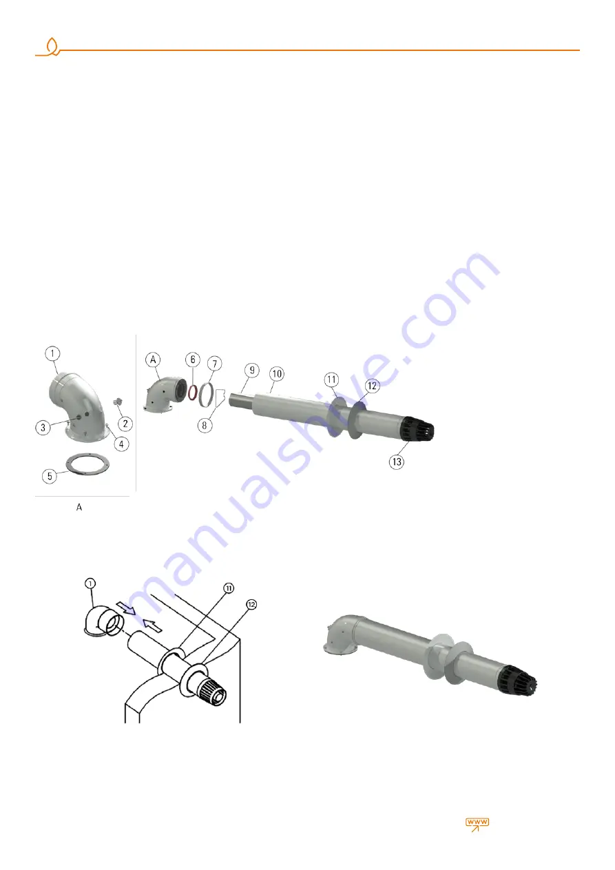
2.2.13. Installation with Horizontal Flue Sets (Ø60/100 mm)

Connecting Horizontal Hermetic Flue Set to the Combi

Since your combi is a hermetic model, it takes the used air from outside 
and discharges exhaust gases created as the result of burning through 
the same flue group. In order to prevent emission of excessively harmful 
exhaust gases, flue usage and installation is very important, therefore 
warnings should be taken into consideration when flue connections are 
being performed.

•  Make required flue selection for the external flue connection If the 

standard flue set is not adequate, please select  most suitable elements 
from our list of connection accessories considering warnings given in our 
user guide.

•  Fix the flange under the elbow piece (1) by using the Flange Bolt (5) via 

Flange Connection Screws (4) to holes on the combi.

•  2 x Ø60 Sealing Gasket within the hermetic flue set (6) are placed into 

internal pipe slots at both ends of the 90° elbow.

•  Place the Ø100 Sealing Gasket (12) on the 90° elbow contacting with the 

restrictive set.

•  Place the External Wall Plate into the flue terminal as seen in Figure 

11-12. for grouping the flue output terminal. After placing the flue output 
terminal through exterior of wall and the previously made hole, fix the 
Internal Wall Plate (11) into the flue terminal. Place, 90° flue elbow of your 
combi coupled tightly to the flue output terminal (Figure 12).  Then fit the 
outer and inner wall flanges (Fig.11_11-12) on the terminal pipe (Fig.12). 
Finally, push the Internal Wall Plate to the wall surface and ensure flue 
and wall impermeability. 

In case the hermetic flue set available in the product package does not 
have adequate length, hermetic flue accessories should be ordered from 
an authorized Warmhaus dealer according to requirements, non-original 
hermetic flue accessories should never be used. 

1.   90° Elbow
2.   Inspection Cap (Gas)
3.   Inspection Cap (Fresh Air)
4. Screws
5.  Neoprene Gasket
6.  Ø60 Sealing Gasket
7.  Ø100 Sealing Gasket
8. Centralizer
9.  Interior Flue Pipe
10.  External Flue Pipe
11.  Internal Wall Plate
12.  External Wall Plate
13. Grill

Figure 12 

Hermetic combi homocentric flue wall output

Figure 13 

Assembled Flue Set

Figure 11 

Hermetic combi homocentric flue set.

Содержание LAWA 18

Страница 1: ...CONVENTIONAL COMBI BOILERS INSTALLATION USER MANUAL LAWA LAWA PLUS...

Страница 2: ...Lawa LawaPlus Enerwa E24 EnerwaPLUSE24...

Страница 3: ...2 2 16 Installation at Partially Protected Exteriors 12 2 2 17 Electrical Connections 12 2 2 18 Optional Controls Room Thermostat External Weather Temperature Sensor and Others 13 2 3 HYDRAULIC INSTA...

Страница 4: ...under any circumstances during installation use or maintenance operations and device warranty shall also be void Only the authorized Warmhaus Service is authorized to make the electrical connection o...

Страница 5: ...r matches Close valves of devices operating with natural gas and your gas meter Immediately evacuate the place with gas odour Natural Gas Emergency Line from your neighbour or another suitable place D...

Страница 6: ...lace Wall installation for the combi boiler should be well secured The hanger plate given as standard with the combi should be installed according to the technique to a full or semi full brick wall ac...

Страница 7: ...abnormal operations Various alloy layers may be formed during transit of LPG gas in tanks depending on mixture compositions That causes a change in heating power of mixture assigned to the device and...

Страница 8: ...er and by using elbows as low as possible At least 1 bar pressurized grid input water should be supplied to ensure adequate domestic hot water Hydrophore should be used if required Figure 10 Flue peri...

Страница 9: ...plications Each 45 elbow usage requires to decrease maximum 50 cm from horizontal vertical distance 60 100 Conventional 90 Elbow 153 11 660 600009 It can be used in horizontal and or vertical flue app...

Страница 10: ...elbow contacting with the restrictive set Place the External Wall Plate into the flue terminal as seen in Figure 11 12 for grouping the flue output terminal After placing the flue output terminal thr...

Страница 11: ...rd Flue Set Elbow 90 b Flue Extension Pipe c Additional 90 Elbow d Standard Flue Set Pipe Figure 16 II Two 90 elbow sample flue installations d a b c a b c d 4 m Figure 15 I Single 90 bended sample fl...

Страница 12: ...Hermetic Flue Type fire resistant insulation material is placed between the wall and exhaust gas relief pipe Materials used for manufacturing the combi are resistant against glycol and propylene based...

Страница 13: ...sockets and extension cables are not allowed to use 2 2 17 Optional Controls Room Thermostat External Weather Temperature Sensor and Others Room thermostat Outside Temperature Sensor etc control devi...

Страница 14: ...of the radiator Combi safety valve relief should be connected to a discharge cone Otherwise safety valve shall be activated and manufacturer shall not be responsible due to water discharge around the...

Страница 15: ...s valve radiator and tap water valves If you will shut off the combi for a short period perform below written operations Do not close combi electrical fuse gas valve radiator and tap water valves Leav...

Страница 16: ...screens consist of navy blue colored backlight LCD screen 2 buttons Radiator 3 and Hot Tap Water 4 and 2 pcs RESET 2 and MODE 1 pushbuttons RESET It is used for re starting the combi and eliminating t...

Страница 17: ...en light turns off At that position you can adjust the temperature between 35 80 C with the Radiator CH temperature adjustment button 3 Temperature value increases when button is rotated clockwise or...

Страница 18: ...if the pressure is lower than this value 18 Failure indicator The temperature value displayed on the combi screen has a 3 C tolerance depending on environmental conditions not arising from the combi...

Страница 19: ...installation Hold the MODE button for switching on the combi when letter is available on the screen A cycle starts on the screen Release the button when cycle is completed In some cases combi initiall...

Страница 20: ...er is seen as the screen screen light turns off your combi is now at STANDBY position Figure 31 Thermostat position Figure 32 Outside weather temperature sensor Figure 33 Outside temperature sensor op...

Страница 21: ...zed Service according to your request Air Discharge Function Activating the menu for LAWA PRIWA and ENERWA models Air discharge function can be activated by pressing the RESET button more than 5 secon...

Страница 22: ...ermittent contacts or open contacts on harness carefully 3 Check Domestic heating water temperature sensor ressistance 4 Check cabeling and connectors between NTC and board 5 Reset Restart boiler E 13...

Страница 23: ...vice at first E 42 Buttons anomaly Boiler does not work E42 error code flashing on the screen Wrong parameters settled on TsP menu 1 Call For service E 43 Opentherm communication error Boiler does not...

Страница 24: ...st perform Au To calibration E 78 Max regulation current value reached Boiler does not work E78 error code flashing on the screen Gas inlet pressure Aging or rust on the electrode Recirculation on flu...

Страница 25: ...Au To calibration E 88 Fault of electronic gas valve managing circuit Boiler does not work E88 error code flashing on the screen Cabeling disconnections Gas valve failiure 1 Call for authorised servi...

Страница 26: ...ration Temporary wind precence 1 If there is strong wind ie wind storm wait until the wind storm stop then keep using the boiler as it is 36 or 48 hours boiler try to remove half power mode by it self...

Страница 27: ...ailures occurring due to transportation unloading loading storing external physical Crushing scratches fractures and chemical factors following delivery of the product 6 Damages and failures arising f...

Страница 28: ...10 7 28 10 32 5 12 8 Max Domestic Hot Water flow rate t 30 C min 10 5 10 9 10 7 10 9 13 9 13 3 13 9 14 2 Maximum Minimum water pressure bar 10 0 3 10 0 3 10 0 3 10 0 3 Temperature adjustment range oC...

Страница 29: ...2ELL I 2H I3P NUMBER OF CHOOSED CONNECTING CONDITIONS Used gas G20 G20 G25 G25 G20 G25 G20 G31 Countries of destination AT BG CH CZ DK EE ES FI GB GR IE IT LT LV NO PT RO SE SI SK DE LU PL RO BE FR NL...

Страница 30: ...30 warmhaus com...

Страница 31: ...been carefully prepared but we reserve the right to make changes and improvements in our products which may affect the accuracy of the information contained in this leaflet All goods are sold subject...

Страница 32: ...CONVENTIONAL COMBI BOILERS INSTALLATION USER MANUAL LAWA LAWA PLUS Instruction booklet code of Lawa LawaPlus 150 11 606 000004 Revision Date 09 2020...

Отзывы: